Ansys
Use guide for Ansys, our team's primary FEA software. Covers the basics such as how to set up a project, but not the technical details of FEA theory.
- Getting Started with Workbench
- 1: Starting a Project
- 2: Mechanical Model System
- 3: Static Structural Analysis
- Notes about nomenclature and symbols
Getting Started with Workbench
Why Ansys?
Ansys is not a program like Solidworks. Rather than having a single viewport to your model open at all times that lets you perform a wide variety of functions, Ansys is segmented into different programs such as mesh, mechanical, and ACP that are accessible through whatever systems you drop into your workbench project.
While this may seem more obtuse than Solidworks where you can quickly take your part and set up a basic simulation, there are many advantage to using Ansys. For example, chassis and roll cage require over 20 simulations of 50+ individual bodies that need to be imported through 3 different part files. Solidworks would require a full reset of the entire model every time a change is made, but with Ansys precise automatic control over what is updated can be done. It also posses much more optimized meshing and solving software that will run better on most computers with less errors. Therefore, we try to use Ansys as much as possible.
What am I looking at?
Ansys starts in Workbench. You may be thinking, what does this have to do with FEA? Where's the CAD model?
In the middle is your project schematic. On the left are your systems. There are a couple kinds of systems, we primarily use the first two:
- Analysis Systems: deal with actual simulations. Most commonly used are Static Structural systems, which deal with the deformation of a system that does not move. Think of a person standing on a bridge.
- Component Systems: deal with setup of the model before putting it into an analysis system. ACP(pre) is very important for composites (chassis), while the geometry and mechanical model systems are very important for structuring efficient workflows (more on that later).
Systems can be dragged and dropped onto the schematic, and links can be dragged between them to create workflows (black and pink lines), where different systems feed data into each other. See how the geometry systems each feed into a mechanical model system, and then 3 mechanical models are combined into 1 before being fed into the actual analysis system. This may seem overly complicated, but is very important to keep the time it takes to reset each simulation every time a part is updated to a minimum.
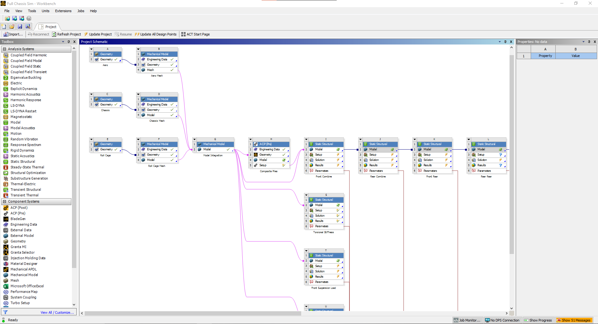
Fig 1. An early example of the full chassis simulation workflow
The systems' properties can be configure on the right panel. Different systems have different options, and will be important for filter what data gets sent to the connected systems
Finally, the red lines feeding out of the analysis systems are parameters (more details later). But basically they simply input/output data in a table format for easy changing of the model or checking if stress is acceptable across iterations.
1: Starting a Project
Importing Geometry
To start a project, either: 1) open Ansys Workbench, or 2) use the Workbench button in Solidworks on whatever model you would like to import. Option one will open a blank project, while option 2 will open a project with a geometry system that is linked to the Solidworks part file.
If you chose option one, the first thing you should do is drop a geometry component system into your project. Right click the geometry step (not the system, more details here), hover over import geometry, and select your desired Solidworks part as seen in figure 1.
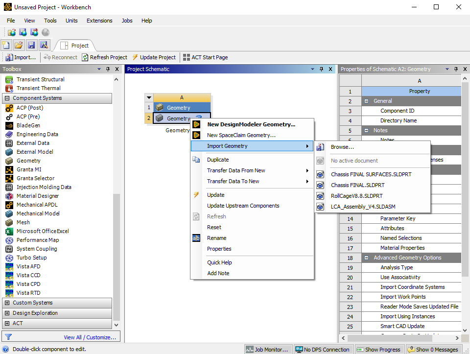
Fig 1. Linking your Solidworks part geometry
This is the first step to any project. There are additional ways to create geometry for simulation by using Ansys's own tools such as DesignModeler of SpaceClaim, but these softwares don't run well for complex parts so we do not use them often. There are however some use cases for them when trying to model very simple projects, but that is not covered in these guides. Additionally other types of general files can be imported such as .step, .iges, etc. but these are not recommended as they do not let you iterate or parameterize your simulation.
If you cannot import a Solidworks method from either option 1 or 2, then you did not set up your CAD interfaces correctly. Go back and do this now before attempting any additional work in Ansys, it will be a waste of your time otherwise. See the install guide for more info.
Working with your linked geometry
Once you've linked the geometry, any changes you make to the model in Solidworks will not update automatically. To bring them into your project, right click the geometry step and click on Update From CAD. This will reprocess the model. Ansys can automatically compensate for small changes such as existing dimension. However, if new faces/bodies are created or renamed for whatever reason, some additional user input will be needed to rerun the project.
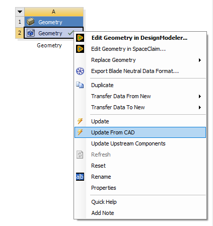
Fig 2. Updating the model from Solidworks to Ansys
2: Mechanical Model System
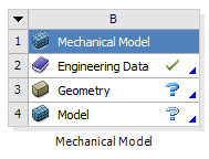
After adding the geometry system, The next component system that should be added is the mechanical model system. This system lets you assign the material, mesh, mesh controls, and named selections.
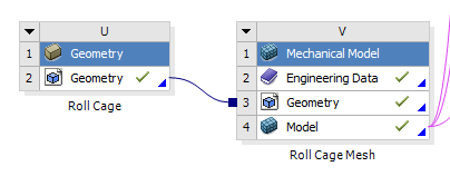
Fig 1. Adding a mechanical model system (right) and linking it to the geometry system
To link the system, click and hold on the geometry step in the geometry system and then drag over to the geometry step in the mechanical model system. We do this so that for more complicated projects you can link the geometry to multiple mechanical models.
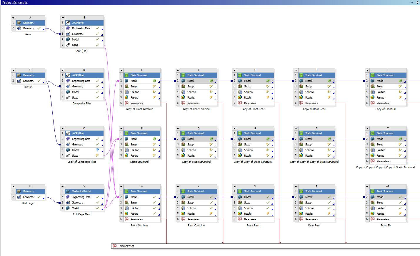
Fig 2. A more complicated project (chassis)
MATERIALS
The engineering data step allows you to select the materials available to apply to your geometry. It will open the materials in the project currently. If plan on using a default material (such as an aluminum or steel alloy) you can skip this step and just add it later in the model step. If you are using a special custom material (such as welded 4130 or carbon fiber-epoxy), it is advisable to add it here.
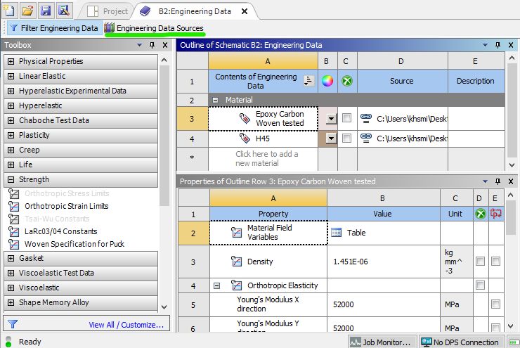
Fig 3. Engineering data page
To select a material, go to engineering data sources (green). This will open a few libraries of materials. You can add one of these existing materials, or create a custom library and then add a custom material. To add a custom material, hit the check box circled in green in figure 4.
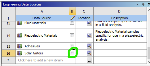
Fig 4. A custom library
Once you have created and named your new custom material, add material properties from the toolbox on the left. Some common ones are under the Linear Elastic and Strength headers. The only values the are required for an isotropic material (such as aluminum or steel) in a typical static structural finite element model are its elastic modulus and Poisson's ratio, which are added with the Isotropic Elasticity property. Yield strength / ultimate strength are required for a factor of safety plot, which may be a result of interest later.
GEOMETRY
This step should already be filled from linking to the geometry system.
MODEL
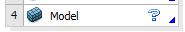
Opening the model step will open an instance of Ansys Mechanical. This is the actual software where the "action" occurs. To move forward and actually analyze the model, all blue question marks must be turned to green checkmarks.
Material assignment
First, materials must be assigned to bodies in the model, either by part or by body. Any material added to engineering data should be available to choose, otherwise use the search bar and materials will be generated via Ansys Granta.
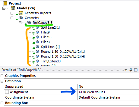
Fig 5. Material is assigned by the blue arrow, either by part (green) or by each individual body (orange).
The materials folder under that is typically not used. The coordinate system folder can be used if you plan to utilize reference points or special coordinate systems for displacement in your model analysis.
Connections
Next, if you have multiple bodies, it is important to verify your connections. Ansys typically automatically generates these, but sometimes they can be wrong. Bad contacts can give massive errors in a model. By default all contacts are assumed to be bonded, i.e. the items are glued together on all 6 degrees of freedom. There are other options for more advanced behavior, but that is not covered here. There are also options for joints, beams, bearings, and springs, which is also not covered here.
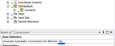
Fig 6. If you want to disable automatic contact generation, change this to NO
Mesh
Lastly, the geometry must be meshed. There are entire research papers dedicated to the best ways to mesh things, and hopefully multiple pages on this wiki (one day), but this will just cover the basics. What is important to know is that a bad mesh can give bad results, so it is important to make sure it properly represents your part.
Meshes are made up of nodes (think the points that connect the lines) and elements (the shapes the connected lines make). There are many different types of elements based on where the nodes are placed, and what geometry is being modeled. 3D parts use either tetrahedrons (triangular pyramids) or hexahedrons (rectangular prisms). 2D parts use either triangles or quadrilaterals. There are also transition elements that exist if a model has both kinds, which is sometimes unavoidable.
Physics preference: Mechanical is the default, and should stay that way unless you are attempting to mesh parts with high amounts of curvature (aeroshell) without mesh control.
Element order: Linear elements only have nodes in the corner. Quadratic elements have a node in the middle of each line. Therefore, linear elements can only model constant strain while quadratic elements can model linear strain. More on that here. A rule of thumb is if you are worried about bending stresses, you either need a very fine linear element model or a less fine quadratic model. It is typically less computationally expensive to use the less fine quadratic model.
Element Size: Element size depends heavily on the model in question. The default size it typically too coarse, but can be a good start for a first run of the model.
These 3 settings are the only basics you need to understand before hitting the generate button.
For additional control, you can right click mesh and insert mesh controls. These are more advanced features which can control where the mesh is seeded from, how it is mapped across faces, and what element method is used. More info on that can be found here.
Mesh Edit
For some models, mesh edits may be necessary. The most common is node matching. This moves nodes between contacting bodies to the same location, which will decrease solution inaccuracy while maintaining mesh and solution speed.
Named Selections
Named selections simply allow you to group bodies, faces, edges, and vertices into a named group that you can call later in your analysis. They are not necessary for most models (required for ACP), but can greatly improve your workflow by minimized the number of times you have to select a large number of items.
FINAL NOTES
A common question is whether to combine all bodies in a model or leave them separate before importing to Ansys for analysis. At the time of writing I (Kurt, Feb 2025) am of the belief that keep the bodies separate is far superior, as long as a fine enough mesh and node matching are used. When bodies are separate, each one's mesh is able to be seeded and verified separately, which means the entire part can be meshed faster. Additionally, the solver can compute each body independently much faster than when all of the bodies are linked.
3: Static Structural Analysis
With all the model setup out of the way, a static structural analysis system can be added. There are lots of other types of analyses, but for the solar car team this is what we typically analyze our parts with, This analysis requires the model not be in motion, i.e. all 6 degrees of freedom are somehow fixed between the included boundary conditions. If this is not true, the model will produce erroneous results.
SYSTEM CREATION
For projects that plan on becoming very large, it is advisable to add this as its own system in the workbench project schematic. For smaller projects with only 1 or 2 load cases, it is fine to just add them within your mechanical model, which will turn the mechanical model into an analysis system. This can be done at the top of the home tab.
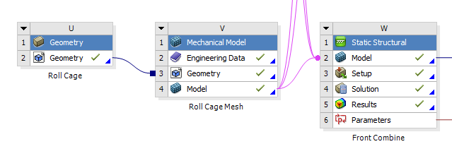
Fig 1. Adding and linking a static structural analysis system in workbench, good for large projects
--- OR ---
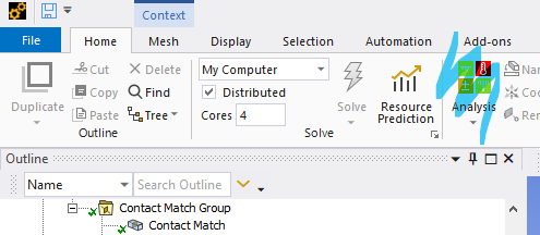
Fig 2. Adding an analysis system within mechanical model, good for small projects
Regardless, the model portion should start with a green checkmark, as that was completed in the previous guide. The only thing that needs user input for this analysis is the setup. By hitting the solve button, the solution will be generated, and then as long as the user has scoped result plots, the results will appear.
SETUP
A finite element analysis (FEA) needs boundary conditions (BCs) to function. These come in many varieties, for a structural analysis, typically in forces and displacements. FEA simply relates the forces in the model to the displacements of the nodes in the model through the model's stiffness. By giving it BCs, it can find all of the displacements and forces within the nodes of the model. From the displacement, strain (the derivative of displacement) and therefore stress can be found.
$k\begin{bmatrix}2 & -1 & -1 & 0 & 0 \\-1 & 3 & -1 & -1 & 0 \\ -1 & -1 & 3 & -1 & 0 \\ 0 & -1 & -1 & 3 & -1 \\ 0 & 0 & 0 & -1 & 1 \end{bmatrix}\begin{Bmatrix}0\\u_2\\u_3\\u_4\\0\end{Bmatrix}=\begin{Bmatrix}R_1\\F_2\\F_3\\F_4\\R_5\end{Bmatrix}$
Fig 3. A simple 1D finite element 5 node bar model matrix, from left to right: stiffness, displacement, force. BCs of 0 displacement on node 1 and 5 are applied
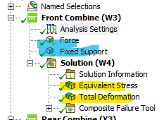
To start, right click on the study and hover over insert. This will pull up a large number of BCs. Most commonly you will use those highlighted in blue (force and fixed support). For more advanced control, those highlighted in pink (remote force and remote displacement) are preferred. However, they actually do the same thing, the second set just gives the user more control over the nodal behavior and degrees of freedom.
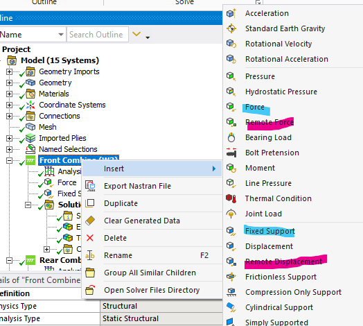
Fig 4. A screenshot of some BCs
Next is result plots. Right click on solution and hover over insert to pull up a list of options. The most common plots utilized are equivalent stress and total deformation.
Analysis Settings
This contains some advanced controls such as what is saved by the solver and how the solver behaves. This may be necessary to modify if advanced result plot such as nodal force, nodal moments, and other plots are desired.
Notes about nomenclature and symbols
This page summarizes the definitions this guide uses for Ansys projects, as well as what some of the symbols you see mean.
Nomenclature
|
System |
|
This entire box is a system. The blue header at the top is how you control the systems overall properties |
|
Step |
|
Each row in the system is a step. Each step has tasks that must be completed within a certain software such as ACP or Mechanical. The step symbol on the right tells you what the step's status is |
Symbols
| Green Check Mark | This means the step is complete. All required information has been selected/input by the user | |
| Filled Blue Question Mark | This means the step needs additional user input to proceed to the next step | |
| Outlined Blue Question Mark | This means a previous step needs additional user input as well as this step | |
| Yellow Bolt | This means the step must be updated to reflect some change, such as meshing or solving | |
| Green Check Mark and Yellow Bolt | This means the step had been complete, but updates from above may cause the data this step holds to change |