Software
A collection of details regarding software installs and various technical how-to-use guides
- SOLIDWORKS
- SOLIDWORKS PDM
- File Organization and Naming Standards for SolidWorks PDM
- How to use PDM (pt. 1)
- How to use PDM (pt. 2)
- Ansys
- Getting Started with Workbench
- 1: Starting a Project
- 2: Mechanical Model System
- 3: Static Structural Analysis
- Notes about nomenclature and symbols
- Finite Element Analysis
- Input Setup for Ansys APDL
- APDL Input Scripts
SOLIDWORKS
Guide for Solidworks use
SOLIDWORKS PDM
Use guide for PDM
File Organization and Naming Standards for SolidWorks PDM
This page outlines the proper structure and naming conventions for organizing files within each subteam’s folder on SolidWorks PDM. If reference is needed, use “Hinge” in PDM. [NOTE: THIS PAGE IS UNDER EDITING]
 Folder Structure
-
[Subteam] Folder
-
-
This is the top-level folder for the respective subteam.
-
-
-
System Folders
-
-
-
-
Each system should have its own dedicated folder within the subteam folder, named after the system (e.g., HINGE).
-
-
-
-
-
There should only be folders at this level within the sub team folder.
-
-
-
-
-
Within Each System Folder
-
-
-
-
-
-
[System Name] DWGs: Contains all parts and assembly drawings for the system.
-
-
-
-
-
-
-
[System Name] ASSY: Contains the system ASSY (assembly), which includes all parts and subassemblies.
-
-
-
-
-
-
-
-
[System Name] OTS: Holds files for over-the-shelf (OTS) parts, i.e., parts that are not custom-made.
-
-
-
-
-
-
-
-
-
-
OTS parts should NOT be renamed from manufactures’ designation.
-
-
-
-
-
-
-
-
-
[System Name] INSTL: The INSTL (installation) file, which is the master assembly mounted onto the entire car i.e. shows the system installation. NOTE: THIS IS AN ASSEMBLY FILE AND SHOULD BE THE ONLY FILE THAT IS NOT A FOLDER AT THIS LEVEL.
-
-
-
File Naming Conventions
-
Custom-Made Parts
-
-
File Name: [Part Name] - [System Name]
-
-
-
Example: DRIVER LINK - HINGE
-
-
Drawing Files
-
-
File Name: [Part Name] - [System Name] DWG
-
-
-
Example: DRIVER LINK - HINGE DWG
-
Example Folder Structure
Auxiliary
-
HINGE
-
HINGE ASSY
-
GROUND LINK - HINGE
-
DRIVER LINK - HINGE
-
HINGE ASSY
-
HINGE OTS
-
Some Bolt 101224
-
Some Nut 163549
-
HINGE INSTL
-
HINGE DWGs
-
GROUND LINK - HINGE DWG
-
DRIVER LINK - HINGE DWG
These guidelines are effective January 2025 in order to ensure the Auxiliary Team can ensure consistency and efficiency when managing files on SolidWorks PDM. If you have any questions or require clarification, please reach out to the team lead.
How to use PDM (pt. 1)
Solidworks PDM is a server based cloud that stores all of the solidworks part files the team designs. It features version control, file check in / check out, and component hierarchy control. If used properly, it works very well. If used improperly, it will ruin you and your lead/chief engineers life.
At all costs, avoid working locally unless absolutely necessary. It saves everyone time in the long run.
This is part 1 of the guide, which covers access and usage relating to it not breaking your whole computer.
Part 2 (here) covers the actual usage of the software in solidworks
GETTING ACCESS:
To start, you need to 1) download the software package and 2) be added to the server as a user with your UF EMAIL. This will allow you to sign in to the blue box that pops up when you try to open the "vault" (what the folder is called). The team typically adds people twice every semester. Don't miss it. And don't use a personal email. The username and password will be whatever your school info is.
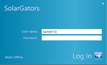
If you can't get the blue box to pop up, right click the vault and hit the "log in" button. You can also right click the vault and hit the "log out" button if you need to log out (more on that later).
NETWORK:
Solidworks PDM requires being on the network that the server is hosted on. In our case, this is being on the UF network in person or VPN. This is what will cause issues with PDM blowing up your computer.
What often happens is you may finish work on something or close your laptop and then your VPN will disconnect, and you will not reconnect it. You are now in purgatory, where your PDM is signed in but you are not on network. If attempt to access your files via file explorer, you may experience either:
1) Very slow functioning file explorer
2) File explorer keeps crashing
3) An endless stream of
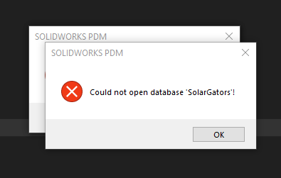
THE ONLY WAY TO FIX THIS IS TO LOG BACK INTO THE UF NETWORK AND THEN SIGN OUT OF PDM MANUALLY
OR
RESTART YOUR COMPUTER
How to use PDM (pt. 2)
Solidworks PDM is a server based cloud that stores all of the solidworks part files the team designs. It features version control, file check in / check out, and component hierarchy control. If used properly, it works very well. If used improperly, it will ruin you and your lead/chief engineers life.
At all costs, avoid working locally unless absolutely necessary. It saves everyone time in the long run.
This is part 2 of the guide, which covers the actual usage of the software in solidworks
Part 1 (here) covers access and usage relating to it not breaking your whole computer.
GETTING PDM TOOLBAR IN SOLIDWORKS
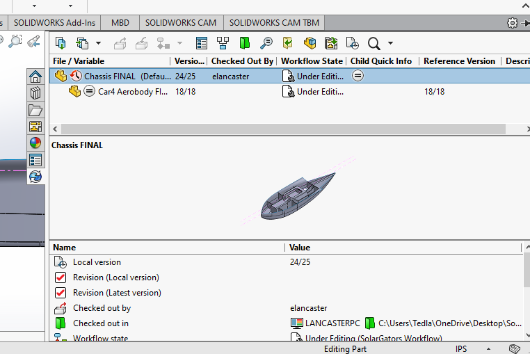
This is most important tool you can add to your Solidworks. It gives you all the information you need about the file, such as what other components it includes, who has what checked out, what version each component is on, etc. It also lets you control these things, allowing you to check in and out included components, open previous versions, get latest version, etc.
To do this, go to tools > add ins and make sure solidworks PDM is checked in both the left and right boxes.
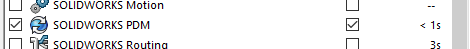
It will appear in the bar on the right side of your screen, make sure you learn how to use it. Hover over the buttons to see what each is, but each function will be covered later in the guide.
PDM CONTROLS
| Function | Color in figure below | Description |
| Check Out | Red | Pulls the file from the server to your computer for editing. Keeps other people from checking out and editing. If you don't do this, the file stays in a read only state. |
| Check In | Green | Puts the file back into the server with whatever changes have been made, and creates a new version. |
| Get Latest | Yellow | Gets the latest version of the file. Typically this is done automatically when checked out or opened, but may need to be done manually in some cases. |
| Get Version | N/A | Gets a specific version from the list of previous versions. |
The following 2 sections deal with opening a file that is not already checked out
OPENING A FILE 1 - small assemblies / basic parts
While in the vault view in file explorer, there are some options available to you. These buttons are typically fine to use, simply highlight the file in question and the buttons will perform the respective action. This method works well for simple parts/assemblies with few to no components/dependencies. If the file is already checked out, the name of the person who has it will be highlighted in the blue area.
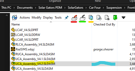
OPENING A FILE 2 - large assemblies / complex parts
For larger files such as assemblies with many components or parts with dependencies, it is better to use the check out window. To access this, do not hit any of the buttons in the vault viewer. Instead, just open the part, this should pull up a window that looks like the figure below.
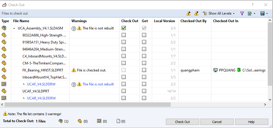
This window lets you control the action being taken for the file in question and every other file included in it. If the file is checked out, then the latest version is automatically "get" -ed. If you want to just view the file, uncheck "check out", but keep "get" checked for the top item. Avoid hitting the cancel button, as this will not "check out" or "get" any of the files.
WORKING ON ASSEMBLIES
When working with files, its important to know what is necessary to be checked out. If you are just adding parts to an assembly, only the assembly needs to be checked out. If you are modifying a part in an assembly, only the part needs to be checked out. However, any rebuilds that happen will not be saved, and there will be a rebuild warning on the assembly next time someone checks out / opens it.
CHECKING IN
Checking in small files is easy, just use the save the part, then use the PDM toolbar in solidworks to check it in before you close it. If you Large assemblies may be more difficult, as others may have parts in the assembly checked out. There are infinite pop ups and warning that might come up when you try to save and check in, so just read them carefully and try to make the best decision that breaks the least things.
Ansys
Use guide for Ansys, our team's primary FEA software. Covers the basics such as how to set up a project, but not the technical details of FEA theory.
Getting Started with Workbench
Why Ansys?
Ansys is not a program like Solidworks. Rather than having a single viewport to your model open at all times that lets you perform a wide variety of functions, Ansys is segmented into different programs such as mesh, mechanical, and ACP that are accessible through whatever systems you drop into your workbench project.
While this may seem more obtuse than Solidworks where you can quickly take your part and set up a basic simulation, there are many advantage to using Ansys. For example, chassis and roll cage require over 20 simulations of 50+ individual bodies that need to be imported through 3 different part files. Solidworks would require a full reset of the entire model every time a change is made, but with Ansys precise automatic control over what is updated can be done. It also posses much more optimized meshing and solving software that will run better on most computers with less errors. Therefore, we try to use Ansys as much as possible.
What am I looking at?
Ansys starts in Workbench. You may be thinking, what does this have to do with FEA? Where's the CAD model?
In the middle is your project schematic. On the left are your systems. There are a couple kinds of systems, we primarily use the first two:
- Analysis Systems: deal with actual simulations. Most commonly used are Static Structural systems, which deal with the deformation of a system that does not move. Think of a person standing on a bridge.
- Component Systems: deal with setup of the model before putting it into an analysis system. ACP(pre) is very important for composites (chassis), while the geometry and mechanical model systems are very important for structuring efficient workflows (more on that later).
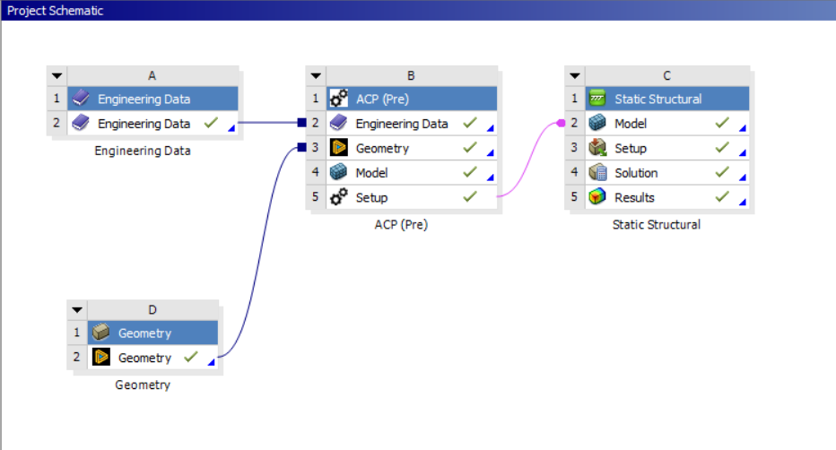
Systems can be dragged and dropped onto the schematic, and links can be dragged between them to create workflows (black and pink lines), where different systems feed data into each other. See how the geometry systems each feed into a mechanical model system, and then 3 mechanical models are combined into 1 before being fed into the actual analysis system. This may seem overly complicated, but is very important to keep the time it takes to reset each simulation every time a part is updated to a minimum.
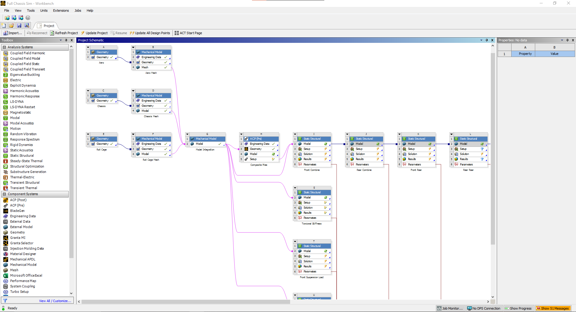
Fig 1. An early example of the full chassis simulation workflow
The systems' properties can be configure on the right panel. Different systems have different options, and will be important for filter what data gets sent to the connected systems
Finally, the red lines feeding out of the analysis systems are parameters (more details later). But basically they simply input/output data in a table format for easy changing of the model or checking if stress is acceptable across iterations.
1: Starting a Project
Importing Geometry
To start a project, either: 1) open Ansys Workbench, or 2) use the Workbench button in Solidworks on whatever model you would like to import. Option one will open a blank project, while option 2 will open a project with a geometry system that is linked to the Solidworks part file.
If you chose option one, the first thing you should do is drop a geometry component system into your project. Right click the geometry step (not the system, more details here), hover over import geometry, and select your desired Solidworks part as seen in figure 1.
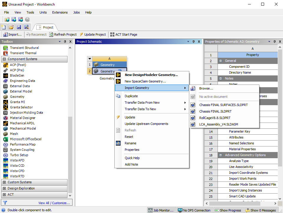
Fig 1. Linking your Solidworks part geometry
This is the first step to any project. There are additional ways to create geometry for simulation by using Ansys's own tools such as DesignModeler of SpaceClaim, but these softwares don't run well for complex parts so we do not use them often. There are however some use cases for them when trying to model very simple projects, but that is not covered in these guides. Additionally other types of general files can be imported such as .step, .iges, etc. but these are not recommended as they do not let you iterate or parameterize your simulation.
If you cannot import a Solidworks method from either option 1 or 2, then you did not set up your CAD interfaces correctly. Go back and do this now before attempting any additional work in Ansys, it will be a waste of your time otherwise. See the install guide for more info.
Working with your linked geometry
Once you've linked the geometry, any changes you make to the model in Solidworks will not update automatically. To bring them into your project, right click the geometry step and click on Update From CAD. This will reprocess the model. Ansys can automatically compensate for small changes such as existing dimension. However, if new faces/bodies are created or renamed for whatever reason, some additional user input will be needed to rerun the project.
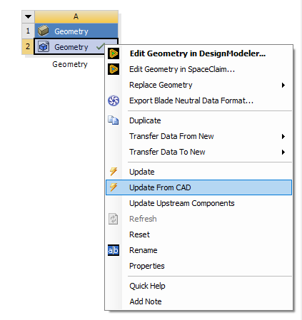
Fig 2. Updating the model from Solidworks to Ansys
2: Mechanical Model System
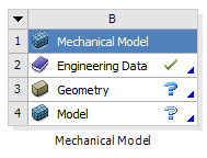
After adding the geometry system, The next component system that should be added is the mechanical model system. This system lets you assign the material, mesh, mesh controls, and named selections.
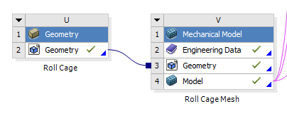
Fig 1. Adding a mechanical model system (right) and linking it to the geometry system
To link the system, click and hold on the geometry step in the geometry system and then drag over to the geometry step in the mechanical model system. We do this so that for more complicated projects you can link the geometry to multiple mechanical models.
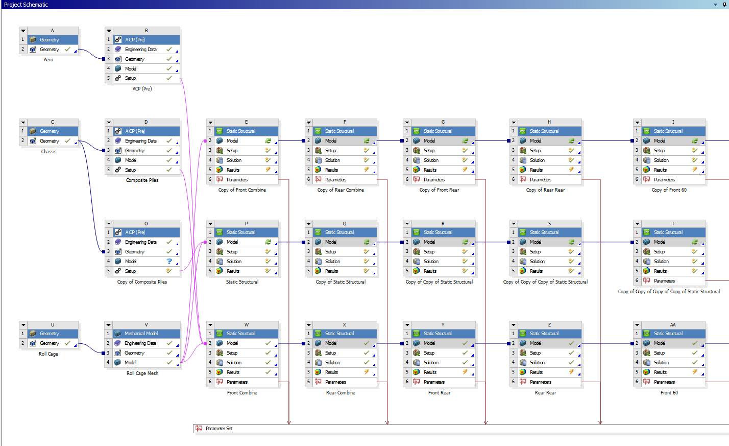
Fig 2. A more complicated project (chassis)
MATERIALS
The engineering data step allows you to select the materials available to apply to your geometry. It will open the materials in the project currently. If plan on using a default material (such as an aluminum or steel alloy) you can skip this step and just add it later in the model step. If you are using a special custom material (such as welded 4130 or carbon fiber-epoxy), it is advisable to add it here.
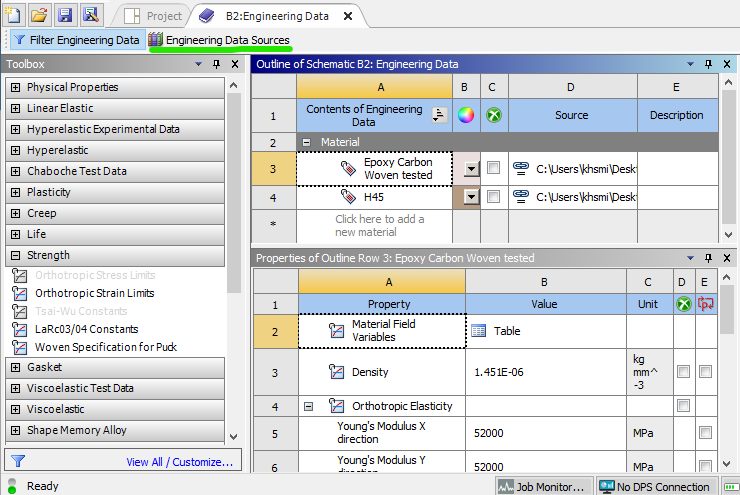
Fig 3. Engineering data page
To select a material, go to engineering data sources (green). This will open a few libraries of materials. You can add one of these existing materials, or create a custom library and then add a custom material. To add a custom material, hit the check box circled in green in figure 4.
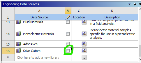
Fig 4. A custom library
Once you have created and named your new custom material, add material properties from the toolbox on the left. Some common ones are under the Linear Elastic and Strength headers. The only values the are required for an isotropic material (such as aluminum or steel) in a typical static structural finite element model are its elastic modulus and Poisson's ratio, which are added with the Isotropic Elasticity property. Yield strength / ultimate strength are required for a factor of safety plot, which may be a result of interest later.
GEOMETRY
This step should already be filled from linking to the geometry system.
MODEL
Opening the model step will open an instance of Ansys Mechanical. This is the actual software where the "action" occurs. To move forward and actually analyze the model, all blue question marks must be turned to green checkmarks.
Material assignment
First, materials must be assigned to bodies in the model, either by part or by body. Any material added to engineering data should be available to choose, otherwise use the search bar and materials will be generated via Ansys Granta.
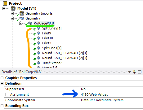
Fig 5. Material is assigned by the blue arrow, either by part (green) or by each individual body (orange).
The materials folder under that is typically not used. The coordinate system folder can be used if you plan to utilize reference points or special coordinate systems for displacement in your model analysis.
Connections
Next, if you have multiple bodies, it is important to verify your connections. Ansys typically automatically generates these, but sometimes they can be wrong. Bad contacts can give massive errors in a model. By default all contacts are assumed to be bonded, i.e. the items are glued together on all 6 degrees of freedom. There are other options for more advanced behavior, but that is not covered here. There are also options for joints, beams, bearings, and springs, which is also not covered here.
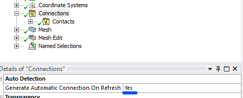
Fig 6. If you want to disable automatic contact generation, change this to NO
Mesh
Lastly, the geometry must be meshed. There are entire research papers dedicated to the best ways to mesh things, and hopefully multiple pages on this wiki (one day), but this will just cover the basics. What is important to know is that a bad mesh can give bad results, so it is important to make sure it properly represents your part.
Meshes are made up of nodes (think the points that connect the lines) and elements (the shapes the connected lines make). There are many different types of elements based on where the nodes are placed, and what geometry is being modeled. 3D parts use either tetrahedrons (triangular pyramids) or hexahedrons (rectangular prisms). 2D parts use either triangles or quadrilaterals. There are also transition elements that exist if a model has both kinds, which is sometimes unavoidable.
Physics preference: Mechanical is the default, and should stay that way unless you are attempting to mesh parts with high amounts of curvature (aeroshell) without mesh control.
Element order: Linear elements only have nodes in the corner. Quadratic elements have a node in the middle of each line. Therefore, linear elements can only model constant strain while quadratic elements can model linear strain. More on that here. A rule of thumb is if you are worried about bending stresses, you either need a very fine linear element model or a less fine quadratic model. It is typically less computationally expensive to use the less fine quadratic model.
Element Size: Element size depends heavily on the model in question. The default size it typically too coarse, but can be a good start for a first run of the model.
These 3 settings are the only basics you need to understand before hitting the generate button.
For additional control, you can right click mesh and insert mesh controls. These are more advanced features which can control where the mesh is seeded from, how it is mapped across faces, and what element method is used. More info on that can be found here.
Mesh Edit
For some models, mesh edits may be necessary. The most common is node matching. This moves nodes between contacting bodies to the same location, which will decrease solution inaccuracy while maintaining mesh and solution speed.
Named Selections
Named selections simply allow you to group bodies, faces, edges, and vertices into a named group that you can call later in your analysis. They are not necessary for most models (required for ACP), but can greatly improve your workflow by minimized the number of times you have to select a large number of items.
FINAL NOTES
A common question is whether to combine all bodies in a model or leave them separate before importing to Ansys for analysis. At the time of writing I (Kurt, Feb 2025) am of the belief that keep the bodies separate is far superior, as long as a fine enough mesh and node matching are used. When bodies are separate, each one's mesh is able to be seeded and verified separately, which means the entire part can be meshed faster. Additionally, the solver can compute each body independently much faster than when all of the bodies are linked.
3: Static Structural Analysis
With all the model setup out of the way, a static structural analysis system can be added. There are lots of other types of analyses, but for the solar car team this is what we typically analyze our parts with, This analysis requires the model not be in motion, i.e. all 6 degrees of freedom are somehow fixed between the included boundary conditions. If this is not true, the model will produce erroneous results.
SYSTEM CREATION
For projects that plan on becoming very large, it is advisable to add this as its own system in the workbench project schematic. For smaller projects with only 1 or 2 load cases, it is fine to just add them within your mechanical model, which will turn the mechanical model into an analysis system. This can be done at the top of the home tab.
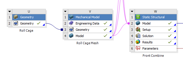
Fig 1. Adding and linking a static structural analysis system in workbench, good for large projects
--- OR ---
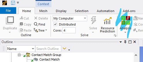
Fig 2. Adding an analysis system within mechanical model, good for small projects
Regardless, the model portion should start with a green checkmark, as that was completed in the previous guide. The only thing that needs user input for this analysis is the setup. By hitting the solve button, the solution will be generated, and then as long as the user has scoped result plots, the results will appear.
SETUP
A finite element analysis (FEA) needs boundary conditions (BCs) to function. These come in many varieties, for a structural analysis, typically in forces and displacements. FEA simply relates the forces in the model to the displacements of the nodes in the model through the model's stiffness. By giving it BCs, it can find all of the displacements and forces within the nodes of the model. From the displacement, strain (the derivative of displacement) and therefore stress can be found.
$k\begin{bmatrix}2 & -1 & -1 & 0 & 0 \\-1 & 3 & -1 & -1 & 0 \\ -1 & -1 & 3 & -1 & 0 \\ 0 & -1 & -1 & 3 & -1 \\ 0 & 0 & 0 & -1 & 1 \end{bmatrix}\begin{Bmatrix}0\\u_2\\u_3\\u_4\\0\end{Bmatrix}=\begin{Bmatrix}R_1\\F_2\\F_3\\F_4\\R_5\end{Bmatrix}$
Fig 3. A simple 1D finite element 5 node bar model matrix, from left to right: stiffness, displacement, force. BCs of 0 displacement on node 1 and 5 are applied
To start, right click on the study and hover over insert. This will pull up a large number of BCs. Most commonly you will use those highlighted in blue (force and fixed support). For more advanced control, those highlighted in pink (remote force and remote displacement) are preferred. However, they actually do the same thing, the second set just gives the user more control over the nodal behavior and degrees of freedom.
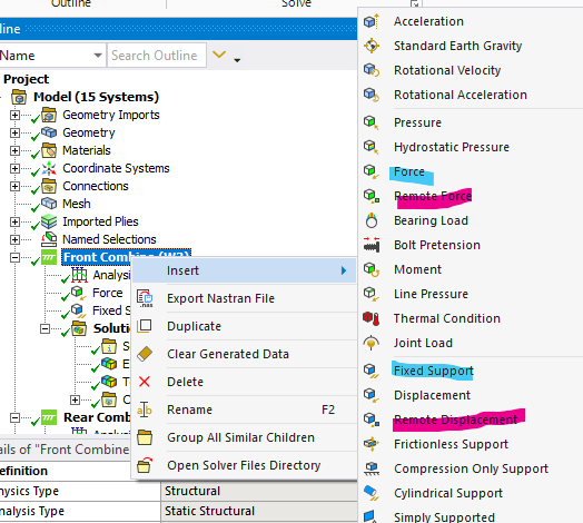
Fig 4. A screenshot of some BCs
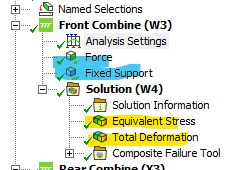
Next is result plots. Right click on solution and hover over insert to pull up a list of options. The most common plots utilized are equivalent stress and total deformation.
Analysis Settings
This contains some advanced controls such as what is saved by the solver and how the solver behaves. This may be necessary to modify if advanced result plot such as nodal force, nodal moments, and other plots are desired.
Notes about nomenclature and symbols
This page summarizes the definitions this guide uses for Ansys projects, as well as what some of the symbols you see mean.
Nomenclature
|
System |
|
This entire box is a system. The blue header at the top is how you control the systems overall properties |
|
Step |
|
Each row in the system is a step. Each step has tasks that must be completed within a certain software such as ACP or Mechanical. The step symbol on the right tells you what the step's status is |
Symbols
| Green Check Mark | This means the step is complete. All required information has been selected/input by the user | |
| Filled Blue Question Mark | This means the step needs additional user input to proceed to the next step | |
| Outlined Blue Question Mark | This means a previous step needs additional user input as well as this step | |
| Yellow Bolt | This means the step must be updated to reflect some change, such as meshing or solving | |
| Green Check Mark and Yellow Bolt | This means the step had been complete, but updates from above may cause the data this step holds to change |
Finite Element Analysis
Guide that covers the finer details and options for running FEA
Basics: 1D Bar Formulation
When solving for the various items of interest using the finite element method (FEM) such as displacement, stress, and strain, it is important to understand the basics of what is happening when you start pressing the various mesh, boundary condition, and solve buttons. In software, these perform very complicated versions of the basics tasks outlined below. Understanding exactly what is happening in each equation and each step is not necessarily super important, as you'll learn the specifics in the FEA class, but this will teach you more about what nodes and elements are.
At the most basic level, the FEM discretizes something into a set of nodes which form elements. The simplest form is a bar element, which represents a 1 dimensional spring with a node at either end and an element between the nodes with stiffness k. This stiffness can be a spring constant k, or if the model represents a real object such as a square bar , k can be calculated from the objects material properties and geometry.
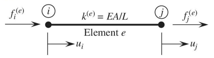
Fig 1. Example bar element
With this model, we can develop a relationship between the forces f and displacements u of the nodes, connected by the element from Hooke's law, which relates spring force to displacement by the spring constant k.
| $f_i=k(u_i-u_j)$ | (1) | |
| $f_j=k(-u_i+u_j)$ | (2) |
These can then be put into a matrix form by pulling out the common k terms and multiplying the displacement terms by an equivalent matrix. Review a numerical methods or linear algebra textbook for a deeper explanation of how matrix math works. This is the common way to represent finite element problems.
| $k\begin{bmatrix}1 & -1 \\-1 & 1\end{bmatrix}\begin{Bmatrix}u_i\\u_j\end{Bmatrix}=\begin{Bmatrix}f_i\\f_j\end{Bmatrix}$ | (3) |
Now this 1D problem can expanded with many nodes and elements chained together, as seen in figure 2. Each local set of nodes with an element between the two has the exact same matrix equation as equation 3. They can each be assembled together into a global matrix, which represents the whole system, where the subscript denotes the nodes and the superscript denotes the elements.
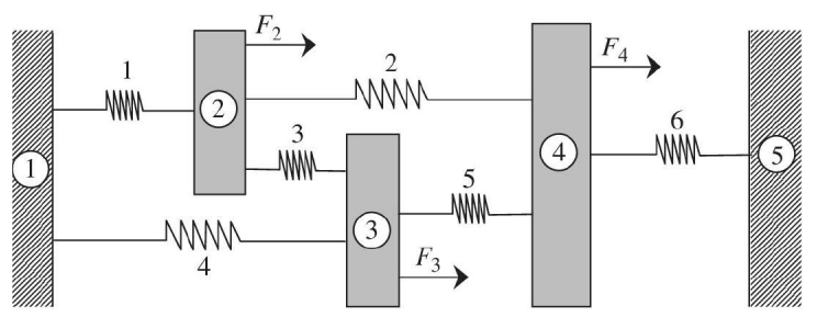
Fig 2. A large system of nodes and elements chained together, with applied forces (2,3,4) and fixed boundaries (1,5)
|
$k\begin{bmatrix}1+1 & -1 & -1 & 0 & 0 \\-1 & 1+1+1 & -1 & -1 & 0 \\ -1 & -1 & 1+1+1 & -1 & 0 \\ 0 & -1 & -1 & 1+1+1 & -1 \\ 0 & 0 & 0 & -1 & 1 \end{bmatrix}\begin{Bmatrix}u_1\\u_2\\u_3\\u_4\\u_5\end{Bmatrix}=\begin{Bmatrix}f_1^{(1)}+f_1^{(4)}\\f_2^{(1)}+f_2^{(2)}+f_2^{(3)}\\f_3^{(3)}+f_3^{(4)}+f_3^{(5)}\\f_4^{(2)}+f_4^{(5)}+f_4^{(6)}\\f_5^{(6)}\end{Bmatrix}$ |
(4) | |
|
$k\begin{bmatrix}2 & -1 & -1 & 0 & 0 \\-1 & 3 & -1 & -1 & 0 \\ -1 & -1 & 3 & -1 & 0 \\ 0 & -1 & -1 & 3 & -1 \\ 0 & 0 & 0 & -1 & 1 \end{bmatrix}\begin{Bmatrix}0\\u_2\\u_3\\u_4\\0\end{Bmatrix}=\begin{Bmatrix}R_1\\F_2\\F_3\\F_4\\R_5\end{Bmatrix}$ |
(5) |
The solution of this becomes fairly simply from the point of equation 5. when the applied forces of 2, 3, and 4 are known and the displacements of 1 and 5 are known to be zero (denoted by the cross hatching), each equation can be read across the rows and solved as a system of equations for the displacements of nodes 2, 3, and 4, and the reactions forces at nodes 1 and 5. This is known as the direct stiffness method.
While this is the simplest type of FEM problem, the use case can be extrapolated to deal with much more complex problems with advanced concepts. In your FEA class, you will start by tackling these 1 dimensional bar problems. More advanced concepts include beams and frames, although new methods using shape equations must be introduced to deal with solving the problems. At the highest level are 2D and 3D elements, which is what is utilized for practical FEA applications on the parts we design.
Input Setup for Ansys APDL
There are many ways to access the APDL section of ansys from a previously existing model or script; this guide will go over one of the more popular methods for accessing APDL from a previous model. This method is typically used for multiple sims with same setup or scripting simulations, it is very convinent when sending simulations aswell.
1. Have the Ansys workbench simulation up and an analysis applied, this one uses static structural :
2. Open Ansys Mechanical :
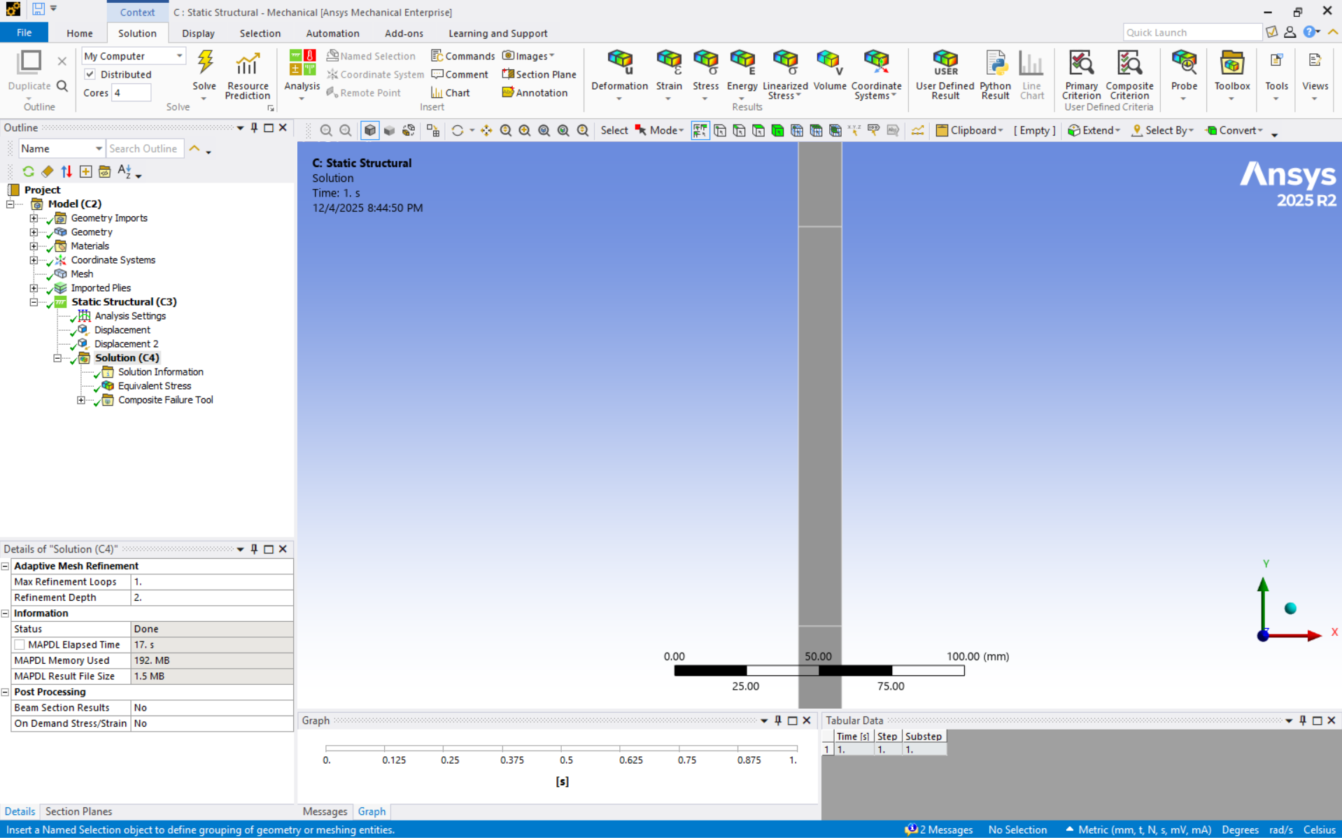
3. Go to the Environment tab in "Static Structural (C3)" or equivalent, and click on write input file. Save the input file as an ".inp" file :

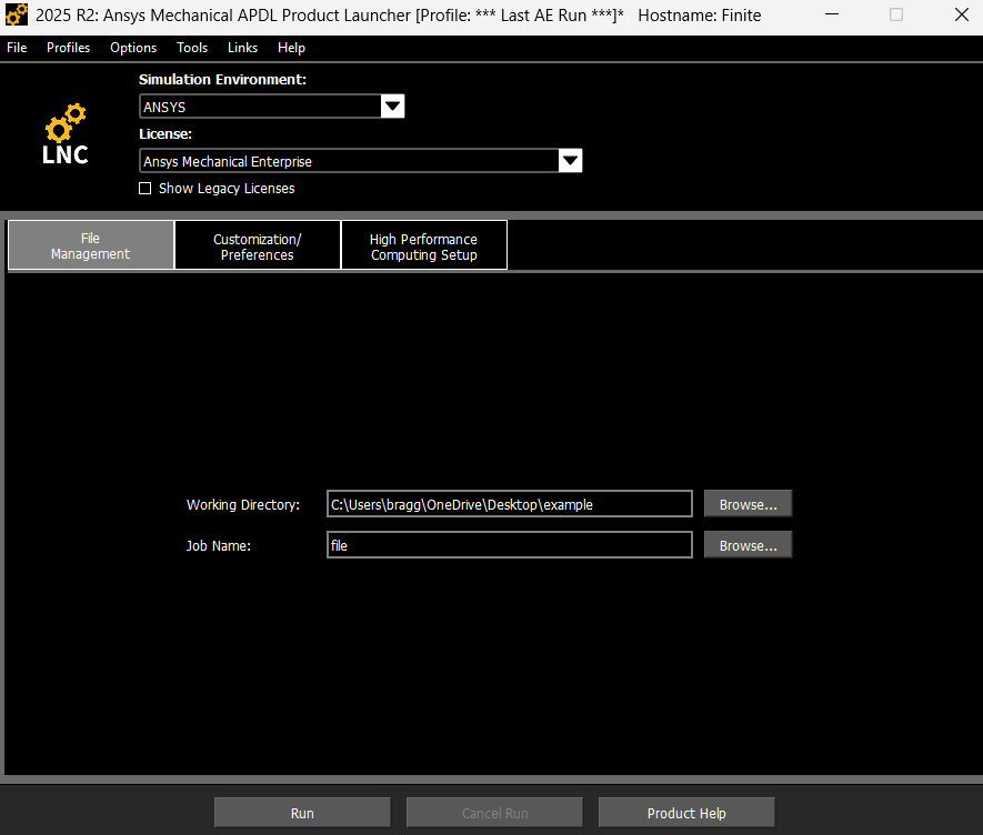
4. Open Ansys Mechanical APDL Product Laucher, choose your working directory, file name and run :
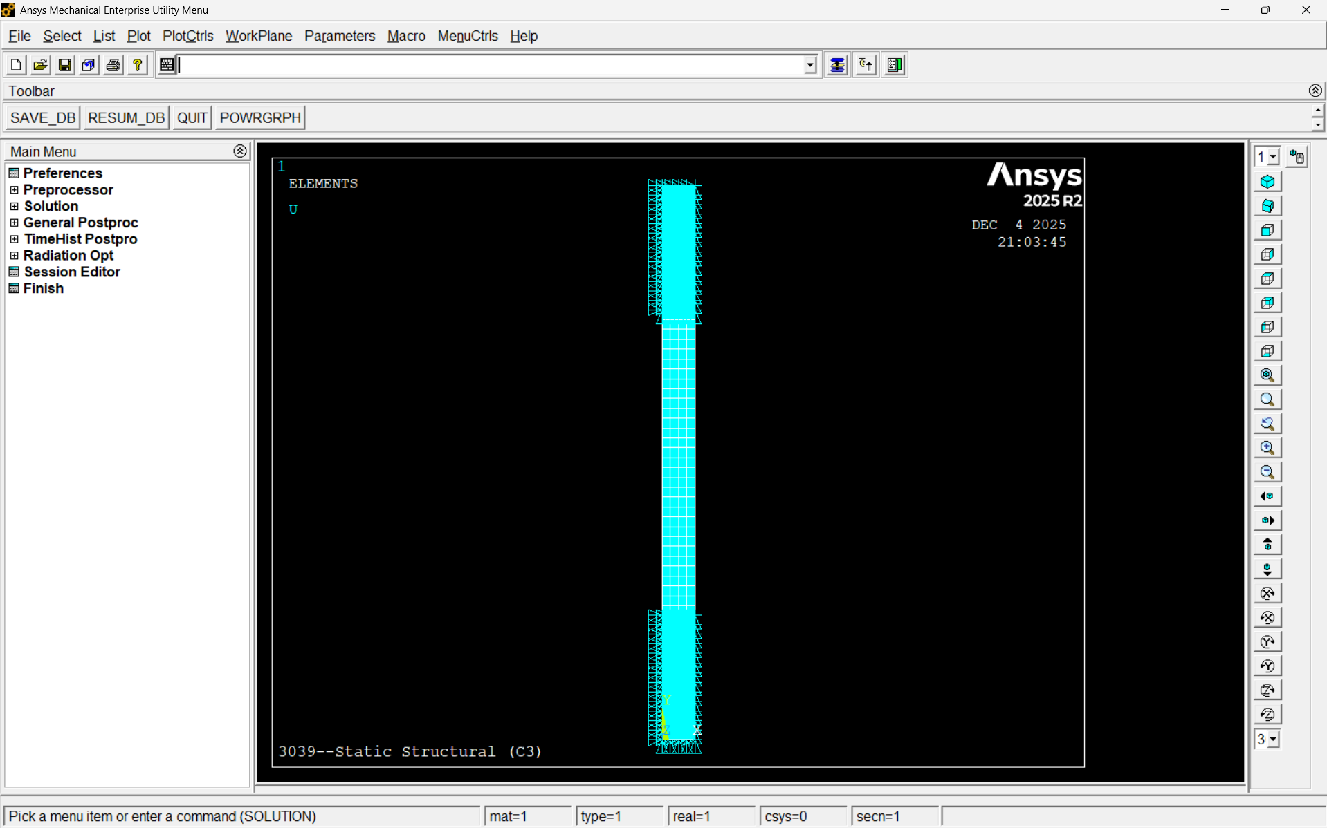
5. In Ansys APDL go to File>Read Input From ...> choose your input file, then type "EPLOT" in the command bar on the top. This will open your workbench simulation into ansys apdl, however there can be element, displacement, force, and node discrepancies between workbench to apdl (stuff workbench does not show you), so please check that everything is right using "DLIST, ELIST, NLIST, FLIST, SFLIST, SFELIST, and equivalent" - especially if you plan to script in apdl. APDL allow you to directly see how your model is operating using commands :
There are alot of weird particulars about this method, but that's for you to figure out :), GL
APDL Input Scripts
Principal Angle Script - run after solution,
! - - -
/POST1
SET,1
! defining all my nodes into a subset, total nodes
ALLSEL,ALL
NSEL,S,,,ALL
CM,totalnodes,node
! defining total number of nodes
*GET,totalnodes_count,NODE,0,COUNT
! List nodes into table
*DIM,LIST,ARRAY,totalnodes_count,1
*VGET, LIST(1), NODE, , NLIST
! define table of stress for each node
PRNSOL,S
*DIM,TABLES,ARRAY,totalnodes_count,4
*DO,I,1,totalnodes_count
*GET,TABLES(I,1),NODE,LIST(I),S,X
*GET,TABLES(I,2),NODE,LIST(I),S,Y
*GET,TABLES(I,3),NODE,LIST(I),S,XY
*AFUN,DEG
r = TABLES(I,3)
q = 0.5*(TABLES(I,1)-TABLES(I,2))
*IF,q,EQ,0,THEN
q = 0.001
*ENDIF
angle = 0.5*ATAN2(r,q)
TABLES(I,4) = ABS(angle)
*ENDDO
! use *VEDIT,TABLES to see table of stresses
! PLOTTING
/POST1
/contour,,10, 2,10,88 ! NCONT=10, VMIN=2, VMAX=90 (uniform spacing)
/dscale,,off
SET,LAST
/GRAPHICS,FULL
*DO,I,1,totalnodes_count
DNSOL,LIST(I),U,X,TABLES(I,4)
*ENDDO
RAPPND,1,1
PLNSOL, U,X, 2,88
! - - -
StrainSpace_AllPlane_Validity_Bidirectional_Fibre - run after solution,
! - - STRESS STATE LEGEND - -
! PRINCIPAL EVERYWHERE
! XY - YELLOW
! YZ - GREEN
! XZ - TEAL
! MULTIPLE - RED
! - - - - - - - - - - - - - -
/POST1
SET,1
! defining all my nodes into a subset, total nodes
ALLSEL,ALL
NSEL,S,,,ALL
CM,totalnodes,node
! defining total number of nodes
*GET,totalnodes_count,NODE,0,COUNT
! List nodes into table
*DIM,LIST,ARRAY,totalnodes_count,1
*VGET, LIST(1), NODE, , NLIST
! define table of stress for each node
PRNSOL,S
*DIM,TABLES,ARRAY,totalnodes_count,6
*DO,I,1,totalnodes_count
*GET,TABLES(I,1),NODE,LIST(I),EPTO,X
*GET,TABLES(I,2),NODE,LIST(I),EPTO,Y
*GET,TABLES(I,3),NODE,LIST(I),EPTO,Z
*GET,TABLES(I,4),NODE,LIST(I),EPTO,XY
*GET,TABLES(I,5),NODE,LIST(I),EPTO,YZ
*GET,TABLES(I,6),NODE,LIST(I),EPTO,XZ
*ENDDO
! list of angles
*DIM,TABLEA,ARRAY,totalnodes_count,3
! xy angle
*DO,I,1,totalnodes_count
*AFUN,DEG
r = TABLES(I,4)/2
q = 0.5*(TABLES(I,1)-TABLES(I,2))
*IF,q,EQ,0,THEN
q = 0.001
*ENDIF
angle = 0.5*ATAN2(r,q)
TABLEA(I,1) = ABS(angle)
*ENDDO
! yz angle
*DO,I,1,totalnodes_count
*AFUN,DEG
r = TABLES(I,5)/2
q = 0.5*(TABLES(I,2)-TABLES(I,3))
*IF,q,EQ,0,THEN
q = 0.001
*ENDIF
angle = 0.5*ATAN2(r,q)
TABLEA(I,2) = ABS(angle)
*ENDDO
! xz angle
*DO,I,1,totalnodes_count
*AFUN,DEG
r = TABLES(I,6)/2
q = 0.5*(TABLES(I,1)-TABLES(I,3))
*IF,q,EQ,0,THEN
q = 0.001
*ENDIF
angle = 0.5*ATAN2(r,q)
TABLEA(I,3) = ABS(angle)
*ENDDO
! index
*DIM,INDEX,ARRAY,totalnodes_count,1
*DO,I,1,totalnodes_count
COUNT_IND = 0
INDEX(I,1) = 0
*IF,TABLEA(I,1),GT,2,AND,TABLEA(I,1),LT,88,THEN ! XY - YELLOW
INDEX(I,1) = 0.8
COUNT_IND = COUNT_IND + 1
*ENDIF
*IF,TABLEA(I,2),GT,2,AND,TABLEA(I,2),LT,88,THEN ! YZ - GREEN
INDEX(I,1) = 0.55
COUNT_IND = COUNT_IND + 1
*ENDIF
*IF,TABLEA(I,3),GT,2,AND,TABLEA(I,3),LT,88,THEN !XZ - TEAL
INDEX(I,1) = 0.30
COUNT_IND = COUNT_IND + 1
*ENDIF
*IF,COUNT_IND,GT,2,THEN ! MULTIPLE - RED
INDEX(I,1) = 1
*ENDIF
*ENDDO
! use *VEDIT,TABLES to see table of stresses
! PLOTTING
/POST1
/contour,,10, 0,1,1 ! NCONT=10, VMIN=2, VMAX=90 (uniform spacing)
/dscale,,off
SET,LAST
/GRAPHICS,FULL
*DO,I,1,totalnodes_count
DNSOL,LIST(I),U,X,INDEX(I,1)
*ENDDO
RAPPND,1,1
PLNSOL, U,X, 0,1
/GLINE,1,-1
/REPLOT
! - - -
StrainSpace_AllPlane_Validity_Unidirectional_Fibre - run after solution,
! - - -
/POST1
SET,1
! defining all my nodes into a subset, total nodes
ALLSEL,ALL
NSEL,S,,,ALL
CM,totalnodes,node
! defining total number of nodes
*GET,totalnodes_count,NODE,0,COUNT
! List nodes into table
*DIM,LIST,ARRAY,totalnodes_count,1
*VGET, LIST(1), NODE, , NLIST
! define table of stress for each node
PRNSOL,S
*DIM,TABLES,ARRAY,totalnodes_count,6
*DO,I,1,totalnodes_count
*GET,TABLES(I,1),NODE,LIST(I),EPTO,X
*GET,TABLES(I,2),NODE,LIST(I),EPTO,Y
*GET,TABLES(I,3),NODE,LIST(I),EPTO,Z
*GET,TABLES(I,4),NODE,LIST(I),EPTO,XY
*GET,TABLES(I,5),NODE,LIST(I),EPTO,YZ
*GET,TABLES(I,6),NODE,LIST(I),EPTO,XZ
*ENDDO
! list of angles
*DIM,TABLEA,ARRAY,totalnodes_count,3
! xy angle
*DO,I,1,totalnodes_count
*AFUN,DEG
r = TABLES(I,4)/2
q = 0.5*(TABLES(I,1)-TABLES(I,2))
*IF,q,EQ,0,THEN
q = 0.001
*ENDIF
angle = 0.5*ATAN2(r,q)
TABLEA(I,1) = ABS(angle)
*ENDDO
! yz angle
*DO,I,1,totalnodes_count
*AFUN,DEG
r = TABLES(I,5)/2
q = 0.5*(TABLES(I,2)-TABLES(I,3))
*IF,q,EQ,0,THEN
q = 0.001
*ENDIF
angle = 0.5*ATAN2(r,q)
TABLEA(I,2) = ABS(angle)
*ENDDO
! xz angle
*DO,I,1,totalnodes_count
*AFUN,DEG
r = TABLES(I,6)/2
q = 0.5*(TABLES(I,1)-TABLES(I,3))
*IF,q,EQ,0,THEN
q = 0.001
*ENDIF
angle = 0.5*ATAN2(r,q)
TABLEA(I,3) = ABS(angle)
*ENDDO
! index
*DIM,INDEX,ARRAY,totalnodes_count,1
*DO,I,1,totalnodes_count
COUNT_IND = 0
INDEX(I,1) = 0
*IF,TABLEA(I,1),GT,2,THEN ! XY
INDEX(I,1) = 0.8
COUNT_IND = COUNT_IND + 1
*ENDIF
*IF,TABLEA(I,2),GT,2,THEN ! YZ
INDEX(I,1) = 0.55
COUNT_IND = COUNT_IND + 1
*ENDIF
*IF,TABLEA(I,3),GT,2,THEN !XZ
INDEX(I,1) = 0.30
COUNT_IND = COUNT_IND + 1
*ENDIF
*IF,COUNT_IND,GT,2,THEN
INDEX(I,1) = 1
*ENDIF
*ENDDO
! use *VEDIT,TABLES to see table of stresses
! PLOTTING
/POST1
/contour,,10, 0,1,1 ! NCONT=10, VMIN=2, VMAX=90 (uniform spacing)
/dscale,,off
SET,LAST
/GRAPHICS,FULL
*DO,I,1,totalnodes_count
DNSOL,LIST(I),U,X,INDEX(I,1)
*ENDDO
RAPPND,1,1
PLNSOL, U,X, 0,1
/GLINE,1,-1
/REPLOT
U_Star_Load_Path_Analysis- run after ajusting "***" indicated lines,
/CLE
*DEL,ALL
! Analyses input starts here
/NOPR ! Suppress printing of UNDO process
FINISH ! Make sure we are at BEGIN level
/PREP7 ! Enter the preprocessor
/OUTPUT,debug,txt ! send all messages to debug.txt (optional)
file_name = 'FILENAUM' ! Change the filename***************************************************************************
NODES_PER_ELEMENT = 20
DOF_PER_NODE = 2 ! 2 - 2D problem ; 3 - 3D problem
!read in the file. the file should contain nodal entity setsl
CDREAD,DB,'C:\Users\bragg\OneDrive\Desktop\Load_Path\RedoOfCode\Load_Path-main\g23plate_fixed',cdb ! ********************************************
EPLOT
!-----------COOKING------------
! SELECT BC
NSEL,U,,,ALL
NSEL,S,D,U,0
CM,fixnodes,NODE
! SELECT FORCES
NSEL,U,,,ALL
NSEL,S,F,F,-1000 ! SAY WHAT MAGNITUDE OF LOAD YOU ARE INPUTTING*************************************
CM,LOADNODES,NODE
!--------------------- GET FREENODES & TOTALNODES ---------------------
ALLSELL,ALL
nsel,all
nsel,u,,,fixnodes
nsel,u,,,loadnodes
CM,freenodes,node
nsel,all
cm,totalnodes,node
!---------------------- Solve the problem ----------------------
/SOLU ! Enter the solution
SOLVE
!--------------------- COUNT THE NODES ---------------------
NSEL,S,,,fixnodes
*GET,fixnodes_count,NODE,0,COUNT
NSEL,S,,,loadnodes
*GET,loadnodes_count,NODE,0,COUNT
NSEL,S,,,freenodes
*GET,freenodes_count,NODE,0,COUNT
NSEL,S,,,totalnodes
*GET,totalnodes_count,NODE,0,COUNT
!--------------------- GET THE NODE NUMBERS ---------------------
NSEL,S,,,loadnodes
*VGET, loadnodes_no, NODE, 0, nlist
NSEL,S,,,fixnodes
*VGET, fixnodes_no, NODE, 0, nlist
NSEL,S,,,freenodes
*VGET, freenodes_no, NODE, 0, nlist
ALLSEL
NSEL,S,,,freenodes ! select freenodes
*GET,min_node_no,NODE,0,NUM,MIN ! Get and assign the least node number of freenodes in the varable "min_node_no"
*DIM,loaded_nodes_lc,ARRAY,2,freenodes_count
!--------------- Apply original boundary conditions ----------------
/PREP7 ! Enter the preprocessor
ALLSEL
D,fixnodes,ALL,0 ! All dofs of the fix nodes to zero (Change according to the problem)
F,loadnodes,Fy,-1000 ! Apply force (Change according to the problem)***************************************
!---------------------- Calculate the strain Energy ----------------------
/POST1
SET,
/POST26
ENERSOL,2,SENE,,STRAINENERGY
FILE,'%file_name%','rst','.'
/UI,COLL,1
NUMVAR,200
SOLU,191,NCMIT
STORE,MERGE
FILLDATA,191,,,,1,1
REALVAR,191,191
*GET,U_VALUE,VARI,2, REAL,1 ! Store the Strain energy value
!---------------------- Calculate the load node displacement ----------------------
*DIM, LOADNODE_DISP,ARRAY,DOF_PER_NODE,loadnodes_count
*IF,DOF_PER_NODE,EQ,2,THEN
*DO, I, 1,loadnodes_count
*GET,LOADNODE_DISP(1,I),NODE,loadnodes_no(I),U,X
*GET,LOADNODE_DISP(2,I),NODE,loadnodes_no(I),U,Y
*ENDDO
*ELSEIF,DOF_PER_NODE,EQ,3,THEN
*DO, I, 1,loadnodes_count
*GET,LOADNODE_DISP(1,I),NODE,loadnodes_no(I),U,X
*GET,LOADNODE_DISP(2,I),NODE,loadnodes_no(I),U,Y
*GET,LOADNODE_DISP(3,I),NODE,loadnodes_no(I),U,Z
*ENDDO
*ENDIF
!---------------------- Do the looping ----------------------
/PREP7 ! Enter the processorer
*DO,I,1,freenodes_count
DDELE,ALL
FDELE,ALL
ALLSEL
!Apply Normal boundary Condition
D,fixnodes,ALL,0 ! All dofs of the fix nodes to zero
*IF,DOF_PER_NODE,EQ,2,THEN
*DO,J,1,loadnodes_count
D,loadnodes_no(J),UX,LOADNODE_DISP(1,J)! assigning enforced X-Displacement at the load nodes
D,loadnodes_no(J),UY,LOADNODE_DISP(2,J)! assigning enforced Y-displacement at the load nodes
*ENDDO
*ELSEIF,DOF_PER_NODE,EQ,3,THEN
*DO,J,1,loadnodes_count
D,loadnodes_no(J),UX,LOADNODE_DISP(1,J)! assigning enforced X-Displacement at the load nodes
D,loadnodes_no(J),UY,LOADNODE_DISP(2,J)! assigning enforced Y-displacement at the load nodes
D,loadnodes_no(J),UZ,LOADNODE_DISP(3,J)! assigning enforced Z-displacement at the load nodes
*ENDDO
*ENDIF
NSEL,S,,,freenodes
loaded_nodes_lc(1,I)=min_node_no
min_node_no=NDNEXT(min_node_no) ! min_node_no(i)= min_node_no(i+1)
D,loaded_nodes_lc(1,I),ALL,ALL
ALLSEL
LSWRITE,I ! Write loadstep
DDELE,ALL ! delete all constrained dofs
*ENDDO
DDELE,ALL
!-------------------- SOLVE ALL THE SETS -------------------------
*GET,TBEFORE,ACTIVE,,TIME,CPU
/SOLU
ALLSEL
LSSOLVE,1,freenodes_count
*GET,TAFTER,ACTIVE,,TIME,CPU
SOLUTION_TIME = (TAFTER-TBEFORE) ! record the computational CPU time
!-------------------- CALCULATE STRAIN ENERGY FOR ALL SET -----------------------
/POST26
! output needs to be redirected to get the list of energies over all load steps
/OUTPUT,energy_list,txt
ENERSOL,3,SENE,,U_PRIME
!PRVAR,3
/OUTPUT ! send the output back again to usual file
!---------------------- ASSIGN U* VALUES TO THE NODES ----------------------
FILE,'%file_name%','rst','.'
/UI,COLL,1
NUMVAR,200
SOLU,191,NCMIT
STORE,MERGE
FILLDATA,191,,,,1,1
REALVAR,191,191
*DO,J,1,freenodes_count ! RECORDING U' PRIME VALUES FOR THE FREENODE
*GET,loaded_nodes_lc(2,J),VARI,3, REAL,J
*ENDDO
*DIM,U_STAR,ARRAY,1,freenodes_count
*DO,K,1,freenodes_count
U_STAR(1,K)= 1 - (U_VALUE/loaded_nodes_lc(2,K)) ! ORIGINAL RATIO
*ENDDO
!---------------------- PLOTTING ----------------------
/POST1
SET,LAST
/GRAPHICS,FULL
*DO,I,1,freenodes_count
DNSOL,freenodes_no(I),U,X,U_STAR(1,I)
*ENDDO
*DO,I,1,loadnodes_count
DNSOL,loadnodes_no(I),U,X,1
*ENDDO
*DO,I,1,fixnodes_count
DNSOL,fixnodes_no(I),U,X,0
*ENDDO
RAPPND,freenodes_count+1,freenodes_count+1
PLNSOL, U,X, 0,1.0
!----------------------------- DATA PROCESSING --------------------
ALLSEL
*GET,ELEM_NO_MIN,ELEM,0,NUM,MIN
*GET,ELEM_NO_MAX,ELEM,0,NUM,MAX
*GET,ELEM_COUNT,ELEM,0,COUNT
ALLSEL
*GET,ELEM_NO_MIN,ELEM,0,NUM,MIN
*GET,ELEM_NO_MAX,ELEM,0,NUM,MAX
*GET,ELEM_COUNT,ELEM,0,COUNT
*DIM,ELEMENT_TABLE,ARRAY,ELEM_COUNT,1+NODES_PER_ELEMENT ! 20 NODES
*DO,I,ELEM_NO_MIN,ELEM_NO_MAX
*SET,ELEMENT_TABLE(I,1),I
*DO,J,1,NODES_PER_ELEMENT
*SET,ELEMENT_TABLE(I,J+1),NELEM(I,J)
*ENDDO
*ENDDO
*DIM,TABLE_RES,ARRAY,totalnodes_count,5
*IF,DOF_PER_NODE,EQ,2,THEN
*DO,I,1,totalnodes_count
*SET,TABLE_RES(I,1),I ! Node Number
*GET,TABLE_RES(I,2),NODE,I,LOC,X ! X- coordinate
*GET,TABLE_RES(I,3),NODE,I,LOC,Y ! Y- coordinate
*SET,TABLE_RES(I,4),0 ! Z- coordinate
*ENDDO
*ELSEIF,DOF_PER_NODE,EQ,3,THEN
*DO,I,1,totalnodes_count
*SET,TABLE_RES(I,1),I ! Node Number
*GET,TABLE_RES(I,2),NODE,I,LOC,X ! X- coordinate
*GET,TABLE_RES(I,3),NODE,I,LOC,Y ! Y- coordinate
*GET,TABLE_RES(I,4),NODE,I,LOC,Z ! Z- coordinate
*ENDDO
*ENDIF
*DO,J,1,freenodes_count
*SET,TABLE_RES(freenodes_no(J),5),U_STAR(1,J)
*ENDDO
*DO,J,1,loadnodes_count
*SET,TABLE_RES(loadnodes_no(J),5),1
*ENDDO
*DO,J,1,fixnodes_count
*SET,TABLE_RES(fixnodes_no(J),5),0
*ENDDO
!-------------------- EXPORTING DATA ---------------------
*cfopen,element_type.txt
! list element types
*GET,net,ETYP,1,NUM,COUNT
*DO,i,1,net
*GET,ETname,ETYP,i,ATTR,ENAM
*VWRITE,'ET ',i,' ',ETname
(A3, F4.0, A1, F4.0)
*ENDDO
*cfclose
*MWRITE,ELEMENT_TABLE,element_table,txt
(F10.0,F10.0,F10.0,F10.0,F10.0,F10.0,F10.0,F10.0,F10.0,F10.0,F10.0,F10.0,F10.0,F10.0,F10.0,F10.0,F10.0,F10.0,F10.0,F10.0,F10.0)
*MWRITE,TABLE_RES,result_table,txt
(F10.0,F10.6,F10.6,F10.6,F10.6)
!6 digit precision. if you want more precision, increase'x' in F10.x
!!!!!!!!!!!!!!!!!!!!!!!!!!!!!!!!!!!!!!!!!!!!!!!!!!!!!!!!!!!!!!!!!!!!!!!!!!!!!!!
! format output for nodes, elements and stress listings
/PAGE, 1E9,, 1E9,, ! disable headers
/FORMAT, , ,14,5, , ! fix floating point format
/HEADER, off, off, off, off, on, off ! disable summaries
!/POST26
!/OUTPUT,NLIST,txt
!NLIST,,,,COORD ! print nodes w. coordinates
!/OUTPUT
!/OUTPUT,ELIST,txt
!ELIST ! print element connectivity table
!/OUTPUT
!/POST1
!/OUTPUT,DISP,txt
!PRNSOL,U ! print all displacements
!/OUTPUT