# Structures

# Adhesion

### **Design Recommendations for Adhesives: 

##### *(Bralla, "DESIGN FOR MANUFACTURABILITY Handbook")*

1\. Design for shear, tension, and compression, not cleavage or peel. Adhesive bonds resist shear, tensile, and compressive forces better than cleavage or peel. Thus the designs shown in Fig. 7.5.2b are preferable to those of Fig. 7.5.2a.

2\. The width of the joint overlap is more important than its length. Bond strength is not proportional to bond area except in cases of pure tension and compression. In a lap joint loaded in shear, the stresses are concentrated at the bond ends. Joint strength therefore is increased more by widening the joint than by lengthening it.

3\. Match expansion coefficients. Large shear stresses are generated when materials with different thermal expansion coefficients are thermally cycled after bonding. Ideally, an adhesive should have an expansion coefficient midway between those of the adherends. Plastics-to-metal bonds may be a problem because of the large differences in thermal expansion of these materials. Fillers are often added to an adhesive to control (usually reduce) its coefficient of expansion. Faster heat-up rates may be possible when the expansion behavior of the adhesive is close to that of the parts.

4\. Thin bond lines are preferred. A thin layer of adhesive is usually advantageous; 25 µm (0.001 in) is typical; thick glue lines consume excess adhesive, have a statistically greater chance for cracks and voids, and do not respond as quickly to temperature changes. An exception would occur when high-impact strength is desired. Then a thicker, more flexible adhesive might well be preferred. This bond line is usually impossible to hit, so I usually hit 10 thou and below and I've heard other people typically hitting 4 or 5 thou.

5\. Design for easy cleaning. Dirty surfaces are a major cause of poor joint performance. Vapor degreasing is a preferred method of preparing surfaces. Solvent wiping may be sufficient if the wipe rags are not allowed to become dirty. Dip cleaning is risky because of the possibility of gradual or sudden contamination of the dip tanks. (See Chap. 8.1 for information on designing parts for easy cleaning.)

6\. Smooth surfaces are preferred. Smooth surfaces are more easily wet by a spreading liquid adhesive. A greater percentage of the area of part surfaces can contact the adhesive when each surface is smooth. Surfaces are often roughened by abrasive treatment before bonding to remove loosely held surface material, even though surface contact with the adhesive is thereby reduced. Loosely held surface layers are the greater evil.

7\. Simple butt joints should be used only when fairly large bond surfaces are involved and when cleavage stresses are not anticipated. Figure 7.5.3 illustrates some of the ways in which a butt joint can be modified to increase resistance to cleavage failure.

8\. When simple lap joints are stressed in tension, they tend to deform as shown in Fig. 7.5.4. This deformation introduces cleavage stresses (for rigid adherends) or peel stresses (for flexible adherends) at the joint ends. Commonly used designs to minimize these stresses are shown in Fig. 7.5.5.

9\. Corner joints involving members of various thicknesses are shown in Fig. 7.5.6. Many variations are possible. The preferred design is usually the one that involves machining or forming operation is offset by the easier cleaning or assembly meth-the least preparation (including handling) cost. Sometimes the cost of an extra ods that may then be possible.

10\. Figure 7.5.7 depicts a number of common techniques for joining rods and tubes adhesively. That design is best which requires the least machining and assembly time. Corners are usually best handled with elbows.

[![20250713_1418202.jpg](https://wiki.ufsolargators.org/uploads/images/gallery/2025-07/scaled-1680-/20250713-1418202.jpg)](https://wiki.ufsolargators.org/uploads/images/gallery/2025-07/20250713-1418202.jpg)[![Screenshot_20250723_005715_Photos.jpg](https://wiki.ufsolargators.org/uploads/images/gallery/2025-07/scaled-1680-/screenshot-20250723-005715-photos.jpg)](https://wiki.ufsolargators.org/uploads/images/gallery/2025-07/screenshot-20250723-005715-photos.jpg)

### **Max Acceleration in G:**

##### *(Roark's Formulas for Stress and Strain)*

[![image.png](https://wiki.ufsolargators.org/uploads/images/gallery/2025-07/scaled-1680-/Ijgimage.png)](https://wiki.ufsolargators.org/uploads/images/gallery/2025-07/Ijgimage.png)

### **CTE Mismatch via all edge constraint:**

##### *(Roark's Formulas for Stress and Strain)*

[![image.png](https://wiki.ufsolargators.org/uploads/images/gallery/2025-07/scaled-1680-/Hoyimage.png)](https://wiki.ufsolargators.org/uploads/images/gallery/2025-07/Hoyimage.png)

Resource for reviewing adhesion: [https://www.stevenabbott.co.uk/practical-adhesion/](https://www.stevenabbott.co.uk/practical-adhesion/)

# Analysis Presentation Format

All analysis presentations should adhere to this format and follow the expectations for each section. This format for peer review was derived from RTX standard presentation formatting and expectations <span class="Yjhzub">—</span> keep it professional.

[![Slide1.PNG](https://wiki.ufsolargators.org/uploads/images/gallery/2025-07/scaled-1680-/slide1.PNG)](https://wiki.ufsolargators.org/uploads/images/gallery/2025-07/slide1.PNG)

[![Slide2.PNG](https://wiki.ufsolargators.org/uploads/images/gallery/2025-07/scaled-1680-/slide2.PNG)](https://wiki.ufsolargators.org/uploads/images/gallery/2025-07/slide2.PNG)

[![Slide3.PNG](https://wiki.ufsolargators.org/uploads/images/gallery/2025-07/scaled-1680-/slide3.PNG)](https://wiki.ufsolargators.org/uploads/images/gallery/2025-07/slide3.PNG)

[![Slide4.PNG](https://wiki.ufsolargators.org/uploads/images/gallery/2025-07/scaled-1680-/slide4.PNG)](https://wiki.ufsolargators.org/uploads/images/gallery/2025-07/slide4.PNG)

[![Slide5.PNG](https://wiki.ufsolargators.org/uploads/images/gallery/2025-07/scaled-1680-/slide5.PNG)](https://wiki.ufsolargators.org/uploads/images/gallery/2025-07/slide5.PNG)

[![Slide6.PNG](https://wiki.ufsolargators.org/uploads/images/gallery/2025-07/scaled-1680-/slide6.PNG)](https://wiki.ufsolargators.org/uploads/images/gallery/2025-07/slide6.PNG)

[![Slide7.PNG](https://wiki.ufsolargators.org/uploads/images/gallery/2025-07/scaled-1680-/slide7.PNG)](https://wiki.ufsolargators.org/uploads/images/gallery/2025-07/slide7.PNG)

[![Slide8.PNG](https://wiki.ufsolargators.org/uploads/images/gallery/2025-07/scaled-1680-/slide8.PNG)](https://wiki.ufsolargators.org/uploads/images/gallery/2025-07/slide8.PNG)

[![Slide9.PNG](https://wiki.ufsolargators.org/uploads/images/gallery/2025-07/scaled-1680-/slide9.PNG)](https://wiki.ufsolargators.org/uploads/images/gallery/2025-07/slide9.PNG)

[![Slide10.PNG](https://wiki.ufsolargators.org/uploads/images/gallery/2025-07/scaled-1680-/slide10.PNG)](https://wiki.ufsolargators.org/uploads/images/gallery/2025-07/slide10.PNG)

[![Slide11.PNG](https://wiki.ufsolargators.org/uploads/images/gallery/2025-07/scaled-1680-/slide11.PNG)](https://wiki.ufsolargators.org/uploads/images/gallery/2025-07/slide11.PNG)

[![Slide12.PNG](https://wiki.ufsolargators.org/uploads/images/gallery/2025-07/scaled-1680-/slide12.PNG)](https://wiki.ufsolargators.org/uploads/images/gallery/2025-07/slide12.PNG)

[![Slide13.PNG](https://wiki.ufsolargators.org/uploads/images/gallery/2025-07/scaled-1680-/slide13.PNG)](https://wiki.ufsolargators.org/uploads/images/gallery/2025-07/slide13.PNG)

# Car 4 Chassis Manufacturing Timeline

### Introduction:

This is documentation of the chassis manufacturing process, method, and failures from our 2025 monoquoce chassis from the prespective of me, Bragg Farmer. The person writing this documentation was the chassis/structures lead of 2024-2025, Bragg Farmer. Here's the document about what happened.  
  
Structures Team 2024-2025:  
Jean Bonet  
Gabriel Brazzeal  
Jacob Cleveland  
Jeremy Delgado  
Allison Donald  
Nhan Hoang  
Richard McCreary  
Callie Monville  
Noah Murphy  
Thomas O'Berc  
Anand Patel  
Joel Reyes  
Henry Reyes-Perez  
Natalia Oliver Sampaio  
Emi Sanchez  
Kurt Smith  
Nuvini Wijesundara  
Jody Zhu  
\- - -  
We cut the foam entirely out of single sheets with no dovetails.

[![20241116_135336.jpg](https://wiki.ufsolargators.org/uploads/images/gallery/2025-07/scaled-1680-/20241116-135336.jpg)](https://wiki.ufsolargators.org/uploads/images/gallery/2025-07/20241116-135336.jpg)

Gluing them together took 2-3 days, i forgot, but the very top piece of foam had to get redone due to regulation mistake. I hadn't glued the top block on yet, so it worked out. I then sanded the glued together foam block with 220 grit sand paper, i believe, and filled as many gaps as I could with spackle.

[![20241121_125033.jpg](https://wiki.ufsolargators.org/uploads/images/gallery/2025-07/scaled-1680-/20241121-125033.jpg)](https://wiki.ufsolargators.org/uploads/images/gallery/2025-07/20241121-125033.jpg)

The mold got spray painted and I hand sanded the mold starting at 220 grit then progressivly going down to 60 then back up to 220, I wanted to make sure not to remove too much material. I would use a bubble level to make sure each side was flat, also would check with all the lights off and light.

[![image.png](https://wiki.ufsolargators.org/uploads/images/gallery/2025-07/scaled-1680-/PImimage.png)](https://wiki.ufsolargators.org/uploads/images/gallery/2025-07/PImimage.png)

The mold had defects so I then would use fairing compound

[![image.png](https://wiki.ufsolargators.org/uploads/images/gallery/2025-07/scaled-1680-/riTimage.png)](https://wiki.ufsolargators.org/uploads/images/gallery/2025-07/riTimage.png)

[![image.png](https://wiki.ufsolargators.org/uploads/images/gallery/2025-07/scaled-1680-/UEqimage.png)](https://wiki.ufsolargators.org/uploads/images/gallery/2025-07/UEqimage.png)

I would work well into the night... and morning to keep on schedule which resulted in the night time photos seen, but this one is of the mold covered in fairing compound. I had to make sure the fairing was actually filling in the defects and not just covering a surface, much attention should be put on this step.

[![image.png](https://wiki.ufsolargators.org/uploads/images/gallery/2025-07/scaled-1680-/zwdimage.png)](https://wiki.ufsolargators.org/uploads/images/gallery/2025-07/zwdimage.png)

[![image.png](https://wiki.ufsolargators.org/uploads/images/gallery/2025-07/scaled-1680-/drXimage.png)](https://wiki.ufsolargators.org/uploads/images/gallery/2025-07/drXimage.png)  
Foam started peaking out in a good amount of spots so I repainted it and didn't use enough hardener so I had to wait a bit to finish (went home for christmas).

[![image.png](https://wiki.ufsolargators.org/uploads/images/gallery/2025-07/scaled-1680-/BOCimage.png)](https://wiki.ufsolargators.org/uploads/images/gallery/2025-07/BOCimage.png)

Resanded and removed any not yet 2 week paint, came out alot smoother than it looked

[![image.png](https://wiki.ufsolargators.org/uploads/images/gallery/2025-07/scaled-1680-/omXimage.png)](https://wiki.ufsolargators.org/uploads/images/gallery/2025-07/omXimage.png)

The suspension holes were meant to be made in the mold then a bolt would be put in to ensure suspension mounting locations would be correct. This did not work due to the paint not puncturing like expect.

[![image.png](https://wiki.ufsolargators.org/uploads/images/gallery/2025-07/scaled-1680-/Zjoimage.png)](https://wiki.ufsolargators.org/uploads/images/gallery/2025-07/Zjoimage.png)

The first layup began an hour before I arrived and was done improperly - never do anything without your lead knowing. The carbon was very dry and heavy.

[![image.png](https://wiki.ufsolargators.org/uploads/images/gallery/2025-07/scaled-1680-/hgnimage.png)](https://wiki.ufsolargators.org/uploads/images/gallery/2025-07/hgnimage.png)

The carbon was kept as we could obtain full vacumm off of it, negating an issue found regarding doing a vaccum bag over a large foam mold - the foam mold has leaks and is mostly air/ lets air in.

[![image.png](https://wiki.ufsolargators.org/uploads/images/gallery/2025-07/scaled-1680-/YTmimage.png)](https://wiki.ufsolargators.org/uploads/images/gallery/2025-07/YTmimage.png)

The carbon mold was painted with epoxy paint and sanded back up to 220 grit

[![image.png](https://wiki.ufsolargators.org/uploads/images/gallery/2025-07/scaled-1680-/Br9image.png)](https://wiki.ufsolargators.org/uploads/images/gallery/2025-07/Br9image.png)

full vaccum

[![image.png](https://wiki.ufsolargators.org/uploads/images/gallery/2025-07/scaled-1680-/nzrimage.png)](https://wiki.ufsolargators.org/uploads/images/gallery/2025-07/nzrimage.png)  
Prepping materials

[![20250215_135203.jpg](https://wiki.ufsolargators.org/uploads/images/gallery/2025-07/scaled-1680-/20250215-135203.jpg)](https://wiki.ufsolargators.org/uploads/images/gallery/2025-07/20250215-135203.jpg)  
prepping layups were done extensivly before the layup

[![image.png](https://wiki.ufsolargators.org/uploads/images/gallery/2025-07/scaled-1680-/UaZimage.png)](https://wiki.ufsolargators.org/uploads/images/gallery/2025-07/UaZimage.png)  
The inner 4 ply was successful but left frog prints and was fixed by cutting out or filling over them

[![image.png](https://wiki.ufsolargators.org/uploads/images/gallery/2025-07/scaled-1680-/dSgimage.png)](https://wiki.ufsolargators.org/uploads/images/gallery/2025-07/dSgimage.png)

large failed plate layup, don't do vaccum bag over cardboard

[![image.png](https://wiki.ufsolargators.org/uploads/images/gallery/2025-07/scaled-1680-/khDimage.png)](https://wiki.ufsolargators.org/uploads/images/gallery/2025-07/khDimage.png)  
First core was placed with breather and would later be sanded off, big mistake, glued to the chassis. Looking back at it, a heat gun would've been better to remove the breather. This mistake would not be made again

[![image.png](https://wiki.ufsolargators.org/uploads/images/gallery/2025-07/scaled-1680-/Jxpimage.png)](https://wiki.ufsolargators.org/uploads/images/gallery/2025-07/Jxpimage.png)

[![image.png](https://wiki.ufsolargators.org/uploads/images/gallery/2025-07/scaled-1680-/qHWimage.png)](https://wiki.ufsolargators.org/uploads/images/gallery/2025-07/qHWimage.png)

[![image.png](https://wiki.ufsolargators.org/uploads/images/gallery/2025-07/scaled-1680-/UBwimage.png)](https://wiki.ufsolargators.org/uploads/images/gallery/2025-07/UBwimage.png)

[![image.png](https://wiki.ufsolargators.org/uploads/images/gallery/2025-07/scaled-1680-/5kvimage.png)](https://wiki.ufsolargators.org/uploads/images/gallery/2025-07/5kvimage.png)

[![image.png](https://wiki.ufsolargators.org/uploads/images/gallery/2025-07/scaled-1680-/RiMimage.png)](https://wiki.ufsolargators.org/uploads/images/gallery/2025-07/RiMimage.png)

[![image.png](https://wiki.ufsolargators.org/uploads/images/gallery/2025-07/scaled-1680-/0jEimage.png)](https://wiki.ufsolargators.org/uploads/images/gallery/2025-07/0jEimage.png)

[![image.png](https://wiki.ufsolargators.org/uploads/images/gallery/2025-07/scaled-1680-/SOGimage.png)](https://wiki.ufsolargators.org/uploads/images/gallery/2025-07/SOGimage.png)  
The cores were spliced using EA9430 with equal parts Qcell and Milled Glass, these would help with dynamic and static viscocity. There were some locations with small amount and some entirely filled, this can be seen in the front of chassis's exposed region if you're curoius.

[![image.png](https://wiki.ufsolargators.org/uploads/images/gallery/2025-07/scaled-1680-/Vfvimage.png)](https://wiki.ufsolargators.org/uploads/images/gallery/2025-07/Vfvimage.png)

[![image.png](https://wiki.ufsolargators.org/uploads/images/gallery/2025-07/scaled-1680-/XB5image.png)](https://wiki.ufsolargators.org/uploads/images/gallery/2025-07/XB5image.png)  
The core with splices was sanded down to be level

[![image.png](https://wiki.ufsolargators.org/uploads/images/gallery/2025-07/scaled-1680-/eUMimage.png)](https://wiki.ufsolargators.org/uploads/images/gallery/2025-07/eUMimage.png)

[![20250318_202215.jpg](https://wiki.ufsolargators.org/uploads/images/gallery/2025-07/scaled-1680-/20250318-202215.jpg)](https://wiki.ufsolargators.org/uploads/images/gallery/2025-07/20250318-202215.jpg)  
The first outer ply was wetted out then applied to the core via a vaccum bag, without vaccumm bag can be seen in the photo below - had to be redone.

[![20250320_131420.jpg](https://wiki.ufsolargators.org/uploads/images/gallery/2025-07/scaled-1680-/20250320-131420.jpg)](https://wiki.ufsolargators.org/uploads/images/gallery/2025-07/20250320-131420.jpg)

[![image.png](https://wiki.ufsolargators.org/uploads/images/gallery/2025-07/scaled-1680-/mXOimage.png)](https://wiki.ufsolargators.org/uploads/images/gallery/2025-07/mXOimage.png)

[![image.png](https://wiki.ufsolargators.org/uploads/images/gallery/2025-07/scaled-1680-/h6Uimage.png)](https://wiki.ufsolargators.org/uploads/images/gallery/2025-07/h6Uimage.png)

SUCCESS, 30 lb+ psi all around, pretty perfect. I was in a haze during the layup, locked in like kyrie on game 7.

[![image.png](https://wiki.ufsolargators.org/uploads/images/gallery/2025-07/scaled-1680-/u3timage.png)](https://wiki.ufsolargators.org/uploads/images/gallery/2025-07/u3timage.png)

[![image.png](https://wiki.ufsolargators.org/uploads/images/gallery/2025-07/scaled-1680-/m9limage.png)](https://wiki.ufsolargators.org/uploads/images/gallery/2025-07/m9limage.png)

[![image.png](https://wiki.ufsolargators.org/uploads/images/gallery/2025-07/scaled-1680-/z2Zimage.png)](https://wiki.ufsolargators.org/uploads/images/gallery/2025-07/z2Zimage.png)

[![image.png](https://wiki.ufsolargators.org/uploads/images/gallery/2025-07/scaled-1680-/1DXimage.png)](https://wiki.ufsolargators.org/uploads/images/gallery/2025-07/1DXimage.png)

[![20250406_145804.jpg](https://wiki.ufsolargators.org/uploads/images/gallery/2025-07/scaled-1680-/20250406-145804.jpg)](https://wiki.ufsolargators.org/uploads/images/gallery/2025-07/20250406-145804.jpg)

datuming was hell. Chassis needed to be in a specific region indicated by bat box panel on aeroshell, but making sure the back plate (that had bow in it) was parallel to the front of chassis and that the chassis was perfectly in the center of a non-datumed aeroshell, everything was curved. I spent a month making sure there was no yaw, roll, or pitch on chassis while ensuring the location of chassis was in the right spot and length.  
Suspension holes were also added via ply wood waterjet with holes

[![image.png](https://wiki.ufsolargators.org/uploads/images/gallery/2025-07/scaled-1680-/eihimage.png)](https://wiki.ufsolargators.org/uploads/images/gallery/2025-07/eihimage.png)

[![image.png](https://wiki.ufsolargators.org/uploads/images/gallery/2025-07/scaled-1680-/0Paimage.png)](https://wiki.ufsolargators.org/uploads/images/gallery/2025-07/0Paimage.png)  
heatgun and scrapping worked very well dure to the polycarb finish on the plates

[![20250426_160300.jpg](https://wiki.ufsolargators.org/uploads/images/gallery/2025-07/scaled-1680-/20250426-160300.jpg)](https://wiki.ufsolargators.org/uploads/images/gallery/2025-07/20250426-160300.jpg)

[![20250505_230550.jpg](https://wiki.ufsolargators.org/uploads/images/gallery/2025-07/scaled-1680-/20250505-230550.jpg)](https://wiki.ufsolargators.org/uploads/images/gallery/2025-07/20250505-230550.jpg)

[![20250406_221939.jpg](https://wiki.ufsolargators.org/uploads/images/gallery/2025-07/scaled-1680-/20250406-221939.jpg)](https://wiki.ufsolargators.org/uploads/images/gallery/2025-07/20250406-221939.jpg)

[![20250407_193953.jpg](https://wiki.ufsolargators.org/uploads/images/gallery/2025-07/scaled-1680-/20250407-193953.jpg)](https://wiki.ufsolargators.org/uploads/images/gallery/2025-07/20250407-193953.jpg)  
Chassis positon was finalized with a laser down the aeroshell up through chassis to the front of the car and many many MANY measurements - triangle measurements.

[![20250424_172326.jpg](https://wiki.ufsolargators.org/uploads/images/gallery/2025-07/scaled-1680-/20250424-172326.jpg)](https://wiki.ufsolargators.org/uploads/images/gallery/2025-07/20250424-172326.jpg)  
The floor was put in by routing out where the floor would be, that was sketched by me, then core was put in with a large EA9430 with filler fillet to allow the last ply to go on well. An inital EA9430 ply was put on then 1 last ply with epoxy (2 in total)

[![image.png](https://wiki.ufsolargators.org/uploads/images/gallery/2025-07/scaled-1680-/pJzimage.png)](https://wiki.ufsolargators.org/uploads/images/gallery/2025-07/pJzimage.png)

[![20250514_152111~2.jpg](https://wiki.ufsolargators.org/uploads/images/gallery/2025-07/scaled-1680-/20250514-1521112.jpg)](https://wiki.ufsolargators.org/uploads/images/gallery/2025-07/20250514-1521112.jpg)  
It was glued in and came out pretty nice, it had some pitch some how but when i weighed it down the dimensions all lined up, this is a mystery to this very day.

[![20250514_192938.jpg](https://wiki.ufsolargators.org/uploads/images/gallery/2025-07/scaled-1680-/20250514-192938.jpg)](https://wiki.ufsolargators.org/uploads/images/gallery/2025-07/20250514-192938.jpg)

[![20250514_192952.jpg](https://wiki.ufsolargators.org/uploads/images/gallery/2025-07/scaled-1680-/20250514-192952.jpg)](https://wiki.ufsolargators.org/uploads/images/gallery/2025-07/20250514-192952.jpg)  
  
I worked every waking moment on this chassis and can't thank enough the people who helped this project come to life.  
However, no one should be expected to put the time I put in, DO NOT START MANUFACTURING CHASSIS AT THE END OF FALL. It should take a year, not 4 months. I finished the chassis mold in roughly 10ish days and spent every moment (usually nights) working on chassis until I left for an internship. It got very painful, get your time tables right.  
  
Thank you everyone on chassis, you are all amazing and I can't thank you enough. Thank you.

# Chassis 2025 Composites Manufacturing Notes

### EA 9340 Guidelines

##### For Adhering Skins to Core

- Roughly 250g glue (not hardener) per 24 sqft of area is the minimum
- More may be required if the skins have wrinkles in them
- Weight is applied via rigid panel and physical weights (i.e. thick plywood + buckets of water)

##### For Fillets

- Roughly 100g glue (not hardener) per 120 inches (one side) of fillet (0.35" radius)
- 5 shots of milled glass per 100g glue to thicken at minimum
- Sand fillet area and tape off outside fillet area before gluing. Apply a thin film of glue on normal surface, but most of the strength comes from the fillet (promotes shear loading)

### Vacuum Bagging

Vacuum is measured in "inches of Mercury" \[inHg\] on our gauges typically. Full vacuum is ~29 inHg. Decent vacuum for our purposes is ~15 inHg. Anything less than that should be avoided. From our experience, venturi pumps can pull a maximum of about 25 inHg.

##### General Use

- All folds or creases create vacuum leaks, avoid at all costs
- When there are vacuum leaks (there are always leaks), pumps have a radius in which they are effective, position pumps effectively so that the area under pressure is maximized
- Put extra breather under frog puck, or else you will a falsely high reading (it suctions itself down onto the surface, decreasing its effective radius)
- Try to vacuum bag on the mold surface at all times, especially for large layups 
    - Examples of what not to do: 
        - Car 4 chassis layup 1 - vacuum bagged on a glass sheet, which encompassed the entire foam mold. Could not pull vacuum because the volume was too large
        - Car 4 flat panel layup 1 - placed polycarbonate sheet on top of cardboard and put duct tape on cardboard, then tried to vacuum bag cardboard/duct tape seam
    - Examples of what to do: 
        - Car 4 chassis layup 2 - vacuum bagged along the very edge of the molded surface, pulled ~10 and 20 inHg depending on which pump's gauge was checked

##### Testing the Bag

- If a bag test is performed (recommended for large layups), it will not indicate useful results unless breather in the bag area during the test
- Oversize the bag so that it can be cut inside the tacky tape line after testing and be reused for the actual layup

# How to depict stress

Engineering has 3 primary stages that every project goes through: Design, Analysis, and Manufacturing. While these are 3 distinct stages, their significance is equal at every stage. When designing a component, one should also consider how to analyze and manufacture such a component; during analysis, changes in design to fix failure and how to manufacture around such changes; during manufacturing, how achieve the goals of design and analysis while dealing with the realities on the ground of manufacturing error. This wiki page is intended to give a wholistic understanding of the theory behind design, analysis, and manufacturing around failure mechanics. The 1<sup>st</sup> <span> </span>section will focus on solid mechanics design and analysis for loads and 2<sup>nd</sup> section being on composites more specifically.

1\. Solid Mechanics

Physics relies on three laws: inertia, F=ma, and force equilibrium. For static analysis, The forces in every component direction (x,y,z) are equal to zero, with boundary conditions to make certain points infinitely stiff/rigid/fixed. The loads experienced on a body are described as normal to the boundary condition (axial)(1) or non-normal to the boundary condition (moment)(2). The only restriction to this method is the requirement to be the number of conditions to be equal or less than the number of component force equations. Generally, the primary method for solving static problems is to take component forces equal to zero in each direction and moments about any point equal to zero to solve for all condition. This is described in more detail and with problems in statics.

<table class="MsoTableGrid" id="bkmrk-%281%29-%282%29" style="border-collapse:collapse;border:none;"><tbody><tr><td style="width:418.25pt;padding:0in 5.4pt 0in 5.4pt;"><span style="font-size:12pt;line-height:115%;font-family:Aptos, sans-serif;">![embedded-image-hcn1svwt.png](https://wiki.ufsolargators.org/uploads/images/gallery/2026-04/embedded-image-hcn1svwt.png)</span>

</td><td style="width:49.25pt;padding:0in 5.4pt 0in 5.4pt;">(1)

</td></tr><tr><td style="width:418.25pt;padding:0in 5.4pt 0in 5.4pt;"><span style="font-size:12pt;line-height:115%;font-family:Aptos, sans-serif;">![embedded-image-omws7sbl.png](https://wiki.ufsolargators.org/uploads/images/gallery/2026-04/embedded-image-omws7sbl.png)</span>

</td><td style="width:49.25pt;padding:0in 5.4pt 0in 5.4pt;">(2)

</td></tr></tbody></table>

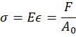
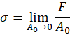
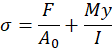
Solid Mechanics/Mechanics of Solids/Mechanics of Materials describes static problems that can be solved with more unknowns than component force equation, using elasticity. MoM describes the internal forces at a point with a 2nd order tensor, called "Stress". Stress is a loose concept that describes the internal forces at a point, with it also being found by the gradient of deflection across elements of a solid. The formulas for engineering stress are described as elasticity/stiffness times strain and as force over area (1). Green-Lagrange/Extensional Strain,<span style="font-size:12pt;line-height:115%;font-family:Aptos, sans-serif;">![embedded-image-kbzxucgc.png](https://wiki.ufsolargators.org/uploads/images/gallery/2026-04/embedded-image-kbzxucgc.png)</span><span>,</span> is the change of length of a specimen divided by the original length (2). Stiffness,<span style="font-size:12pt;line-height:115%;font-family:Aptos, sans-serif;">![embedded-image-cwtflrul.png](https://wiki.ufsolargators.org/uploads/images/gallery/2026-04/embedded-image-cwtflrul.png)</span><span>,</span> is a value describing a material’s resistance to deformation. The other form uses force,<span style="font-size:12pt;line-height:115%;font-family:Aptos, sans-serif;">![embedded-image-xmt56ars.png](https://wiki.ufsolargators.org/uploads/images/gallery/2026-04/embedded-image-xmt56ars.png)</span><span>,</span> applied divided by some constant area,<span style="font-size:12pt;line-height:115%;font-family:Aptos, sans-serif;">![embedded-image-gdydzdaa.png](https://wiki.ufsolargators.org/uploads/images/gallery/2026-04/embedded-image-gdydzdaa.png)</span><span>. The force over area variation is actually average engineering stress across a constant area, so for an accurate stress value to be true the distribution of stress across the area must be the same. Finite element method decomposes geometry into a mesh with elements of ever decreasing area to zero, which is where stress singularizes occur as the model converges and the stress goes to infinity (3).</span> This stress described is stress about the normal axis defined by a given plane, called normal stress.

<table class="MsoTableGrid" id="bkmrk-%281%29-%282%29-%283%29" style="border-collapse:collapse;border:none;"><tbody><tr><td style="width:368.75pt;padding:0in 5.4pt 0in 5.4pt;"><span style="font-size:12pt;line-height:115%;font-family:Aptos, sans-serif;">![embedded-image-sthnmyef.png](https://wiki.ufsolargators.org/uploads/images/gallery/2026-04/embedded-image-sthnmyef.png)</span>

</td><td style="width:98.75pt;padding:0in 5.4pt 0in 5.4pt;">(1)

</td></tr><tr><td style="width:368.75pt;padding:0in 5.4pt 0in 5.4pt;"><span style="font-size:12pt;line-height:115%;font-family:Aptos, sans-serif;">![embedded-image-0g73yhvc.png](https://wiki.ufsolargators.org/uploads/images/gallery/2026-04/embedded-image-0g73yhvc.png)</span>

</td><td style="width:98.75pt;padding:0in 5.4pt 0in 5.4pt;">(2)

</td></tr><tr><td style="width:368.75pt;padding:0in 5.4pt 0in 5.4pt;"><span style="font-size:12pt;line-height:115%;font-family:Aptos, sans-serif;">![embedded-image-uqnst6bf.png](https://wiki.ufsolargators.org/uploads/images/gallery/2026-04/embedded-image-uqnst6bf.png)</span>

</td><td style="width:98.75pt;padding:0in 5.4pt 0in 5.4pt;">(3)

</td></tr></tbody></table>

<span>![embedded-image-dyjln1q4.png](https://wiki.ufsolargators.org/uploads/images/gallery/2026-04/embedded-image-dyjln1q4.png)</span>

<span> </span>Given a body (Fig. 1), how would someone find stress? First, the boundary conditions can be fixed: displacement in every direction equal to zero and rotation in every direction equal to zero. Load can be applied as a force at a point, force across a length, or force across an area; these three methods are interchange able for applying a load on a body with each method only applying unity for any given length unused (unity is any value equal to 1, so force across length will have a depth equal to unity/1).

<span>![embedded-image-lriuppba.png](https://wiki.ufsolargators.org/uploads/images/gallery/2026-04/embedded-image-lriuppba.png)</span>

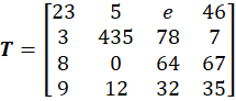
To find stress, we must first go over how stress is a 2<sup>nd</sup> order tensor. A tensor is an array with an implied magnitude and an order equal to the dimensions applied. So, a scalar/magnitude will be a 0<sup>th</sup> order tensor (1); a 1<sup>st</sup> order tensor will be an array of magnitudes with columns (2); a 2<sup>nd</sup> order tensor will be an array of magnitudes with rows and columns (3). Stress is a 2<sup>nd</sup> order tensor, with the first dimension being a plane to take stress on and the second being a direction to take stress in (4); <span style="font-size:12pt;line-height:115%;font-family:Aptos, sans-serif;">![embedded-image-6tmomsbu.png](https://wiki.ufsolargators.org/uploads/images/gallery/2026-04/embedded-image-6tmomsbu.png)</span>.

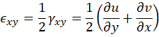
Normal stress,<span style="font-size:12pt;line-height:115%;font-family:Aptos, sans-serif;">![embedded-image-xsnof40u.png](https://wiki.ufsolargators.org/uploads/images/gallery/2026-04/embedded-image-xsnof40u.png)</span>,is stress taken about the normal vector/direction, and Shear stress,<span style="font-size:12pt;line-height:115%;font-family:Aptos, sans-serif;">![embedded-image-oqlrqrhv.png](https://wiki.ufsolargators.org/uploads/images/gallery/2026-04/embedded-image-oqlrqrhv.png)</span><span>,</span> is stress taken about any other unit vector/direction. Normal stress applies a linear elastic response/normal strain (<span style="font-size:12pt;line-height:115%;font-family:Aptos, sans-serif;">![embedded-image-ey4qiddz.png](https://wiki.ufsolargators.org/uploads/images/gallery/2026-04/embedded-image-ey4qiddz.png)</span><span>)</span>, which was described previously as change of length over original length. Shear stress applies a distortional elastic response and describes shear stain (<span style="font-size:12pt;line-height:115%;font-family:Aptos, sans-serif;">![embedded-image-tqyniwi1.png](https://wiki.ufsolargators.org/uploads/images/gallery/2026-04/embedded-image-tqyniwi1.png)</span>) as the change of angle between two originally orthogonal axes (5).

<table class="MsoTableGrid" id="bkmrk-%281%29-%282%29-%283%29-%284%29-%285%29" style="border-collapse:collapse;border:none;"><tbody><tr><td style="width:436.25pt;border:none;padding:0in 5.4pt 0in 5.4pt;"><span style="font-size:12pt;line-height:115%;font-family:Aptos, sans-serif;">![embedded-image-slrnrnim.png](https://wiki.ufsolargators.org/uploads/images/gallery/2026-04/embedded-image-slrnrnim.png)</span>

</td><td style="width:31.25pt;border:none;padding:0in 5.4pt 0in 5.4pt;">(1)

</td></tr><tr><td style="width:436.25pt;border:none;padding:0in 5.4pt 0in 5.4pt;"><span style="font-size:12pt;line-height:115%;font-family:Aptos, sans-serif;">![embedded-image-kqdaj8yw.png](https://wiki.ufsolargators.org/uploads/images/gallery/2026-04/embedded-image-kqdaj8yw.png)</span>

</td><td style="width:31.25pt;border:none;padding:0in 5.4pt 0in 5.4pt;">(2)

</td></tr><tr><td style="width:436.25pt;border:none;padding:0in 5.4pt 0in 5.4pt;"><span style="font-size:12pt;line-height:115%;font-family:Aptos, sans-serif;">![embedded-image-0qosb6yg.png](https://wiki.ufsolargators.org/uploads/images/gallery/2026-04/embedded-image-0qosb6yg.png)</span>

</td><td style="width:31.25pt;border:none;padding:0in 5.4pt 0in 5.4pt;">(3)

</td></tr><tr><td style="width:436.25pt;border:none;padding:0in 5.4pt 0in 5.4pt;"><span style="font-size:12pt;line-height:115%;font-family:Aptos, sans-serif;">![embedded-image-oggtmuva.png](https://wiki.ufsolargators.org/uploads/images/gallery/2026-04/embedded-image-oggtmuva.png)</span>

</td><td style="width:31.25pt;border:none;padding:0in 5.4pt 0in 5.4pt;">(4)

</td></tr><tr><td style="width:436.25pt;border:none;padding:0in 5.4pt 0in 5.4pt;"><span style="font-size:12pt;line-height:115%;font-family:Aptos, sans-serif;">![embedded-image-p2bdsnz9.png](https://wiki.ufsolargators.org/uploads/images/gallery/2026-04/embedded-image-p2bdsnz9.png)</span>

<span style="font-size:12pt;line-height:115%;font-family:Aptos, sans-serif;">![embedded-image-lrqp67lg.png](https://wiki.ufsolargators.org/uploads/images/gallery/2026-04/embedded-image-lrqp67lg.png)</span>

</td><td style="width:31.25pt;border:none;padding:0in 5.4pt 0in 5.4pt;">(5)

</td></tr></tbody></table>

<span style="margin-left:235px;margin-top:860px;width:119px;height:49px;"></span><span>![embedded-image-skymdcfb.png](https://wiki.ufsolargators.org/uploads/images/gallery/2026-04/embedded-image-skymdcfb.png)![embedded-image-vmmjuzcw.png](https://wiki.ufsolargators.org/uploads/images/gallery/2026-04/embedded-image-vmmjuzcw.png)</span>

<span>![embedded-image-2mxun67y.png](https://wiki.ufsolargators.org/uploads/images/gallery/2026-04/embedded-image-2mxun67y.png)</span>

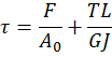
The core idea for normal and shear load/stress/strain, is how normal loading applies linear response and equation and shear applies distortional response and equations. For design, one should view loads as either normal or shear. With normal loads being applied from axial (on axis is when the normal vector is in the direction of the load) or bend-moment loads (1). Shear loads are applied via off-axis (off axis referring to when the unit vector is taken not in the direction of the load) or torsional loads (2). Stress is taken at a point that can be represented in the form of 3 mutually perpendicular planes with associated stress and strain components. For more reference of how to solve for stresses in real problems, look for combined loading problems in mechanics of materials textbooks.

<table class="MsoTableGrid" id="bkmrk-%281%29-%282%29-1" style="border-collapse:collapse;border:none;"><tbody><tr><td style="width:404.75pt;padding:0in 5.4pt 0in 5.4pt;"><span style="font-size:12pt;line-height:115%;font-family:Aptos, sans-serif;">![embedded-image-jq1zrcsj.png](https://wiki.ufsolargators.org/uploads/images/gallery/2026-04/embedded-image-jq1zrcsj.png)</span>

</td><td style="width:62.75pt;padding:0in 5.4pt 0in 5.4pt;">(1)

</td></tr><tr><td style="width:404.75pt;padding:0in 5.4pt 0in 5.4pt;"><span style="font-size:12pt;line-height:115%;font-family:Aptos, sans-serif;">![embedded-image-e3ahhryh.png](https://wiki.ufsolargators.org/uploads/images/gallery/2026-04/embedded-image-e3ahhryh.png)</span>

</td><td style="width:62.75pt;padding:0in 5.4pt 0in 5.4pt;">(2)

</td></tr></tbody></table>

<span>![Six independent stress components of an infinitely small 3D element. |  Download Scientific Diagram](https://wiki.ufsolargators.org/uploads/images/gallery/2026-04/embedded-image-6teocgfc.png)</span>

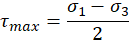
Now we know what stress is an how to find it, but how do we find max stress. For 2D problems, this can be done with a Morh’s circle/Morh space. The axes are normal stress in the x and shear stress in the y. You can apply your state of stress on the plot and find the maximum stress/principal stresses,<span style="font-size:12pt;line-height:115%;font-family:Aptos, sans-serif;">![embedded-image-29nqaean.png](https://wiki.ufsolargators.org/uploads/images/gallery/2026-04/embedded-image-29nqaean.png)</span>,(where shear is zero) and find the maximum shear stress,<span style="font-size:12pt;line-height:115%;font-family:Aptos, sans-serif;">![embedded-image-tz94lmxh.png](https://wiki.ufsolargators.org/uploads/images/gallery/2026-04/embedded-image-tz94lmxh.png)</span>. You find the principal stresses by transforming the stress state into the principal direction using stress transformation (1). This can be seen as transforming the stress tensor into a tensor with no shear stress components, as principal stress are mutually perpendicular unit vectors so long as the principal stresses are distinct from one another. The maximum shear stress is found as the midpoint between the first and third principal stresses - as they descend in magnitude from 1 to 3 (2). Principal stresses can also be found using invariants and factors of zero, values that do not change with coordinate system (3).

<table class="MsoTableGrid" id="bkmrk-%281%29-%282%29-%C2%A0-%C2%A0-%C2%A0-%C2%A0-%283%29" style="border-collapse:collapse;border:none;"><tbody><tr><td style="width:301.25pt;padding:0in 5.4pt 0in 5.4pt;"><span style="font-size:12pt;line-height:115%;font-family:Aptos, sans-serif;">![embedded-image-3fw9kyam.png](https://wiki.ufsolargators.org/uploads/images/gallery/2026-04/embedded-image-3fw9kyam.png)</span>

</td><td style="width:166.25pt;padding:0in 5.4pt 0in 5.4pt;">(1)

</td></tr><tr><td style="width:301.25pt;padding:0in 5.4pt 0in 5.4pt;"><span style="font-size:12pt;line-height:115%;font-family:Aptos, sans-serif;">![embedded-image-66dbsymc.png](https://wiki.ufsolargators.org/uploads/images/gallery/2026-04/embedded-image-66dbsymc.png)</span>

</td><td style="width:166.25pt;padding:0in 5.4pt 0in 5.4pt;">(2)

</td></tr><tr><td style="width:301.25pt;padding:0in 5.4pt 0in 5.4pt;">*<span style="font-family:'Cambria Math', serif;"><span> </span></span>*<span style="font-size:12pt;line-height:115%;font-family:Aptos, sans-serif;">![embedded-image-2fdfouee.png](https://wiki.ufsolargators.org/uploads/images/gallery/2026-04/embedded-image-2fdfouee.png)</span>

<span style="font-size:12pt;line-height:115%;font-family:Aptos, sans-serif;">![embedded-image-qxw03z7k.png](https://wiki.ufsolargators.org/uploads/images/gallery/2026-04/embedded-image-qxw03z7k.png)</span>*<span style="font-family:'Cambria Math', serif;"><span> </span></span>*

*<span style="font-family:'Cambria Math', serif;"><span> </span></span>*<span style="font-size:12pt;line-height:115%;font-family:Aptos, sans-serif;">![embedded-image-9mhhznq3.png](https://wiki.ufsolargators.org/uploads/images/gallery/2026-04/embedded-image-9mhhznq3.png)</span>

*<span style="font-family:'Cambria Math', serif;"><span> </span></span>*<span style="font-size:12pt;line-height:115%;font-family:Aptos, sans-serif;">![embedded-image-key4w7iz.png](https://wiki.ufsolargators.org/uploads/images/gallery/2026-04/embedded-image-key4w7iz.png)</span>

</td><td style="width:166.25pt;padding:0in 5.4pt 0in 5.4pt;">(3)

</td></tr></tbody></table>

<span style="margin-left:646px;margin-top:1408px;width:169px;height:49px;"></span><span style="margin-left:277px;margin-top:1407px;width:119px;height:49px;"></span><span>![embedded-image-ocgimrxc.png](https://wiki.ufsolargators.org/uploads/images/gallery/2026-04/embedded-image-ocgimrxc.png)</span><span> </span><span>![embedded-image-cxs4uo3v.png](https://wiki.ufsolargators.org/uploads/images/gallery/2026-04/embedded-image-cxs4uo3v.png)</span>

Solid mechanics uses an elastostatic boundary value problem, where the strains can be found once the displacement are determined using strain displacement relations, and stress can be found using constitutive relations. These kind of problems involve solving 3 equilibrium equations in conjunction with strain-displacement relations and constitutive relations. The boundary conditions need to be provided in terms of given displacements or prescribed forces.

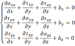
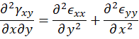
There are 6 stress functions that can not be arbitrary and are calculated using stress equilibrium equations, these equations are called stress fields (1). The assumptions are that the out of plane stress is unity and there are body forces (gravity and such). They are solved by taking the 2<sup>nd</sup> order Taylor series approximation of the differential stress element.

<table class="MsoTableGrid" id="bkmrk-%281%29" style="border-collapse:collapse;border:none;"><tbody><tr><td style="width:382.25pt;padding:0in 5.4pt 0in 5.4pt;"><span style="font-size:12pt;line-height:115%;font-family:Aptos, sans-serif;">![embedded-image-ibzbnwst.png](https://wiki.ufsolargators.org/uploads/images/gallery/2026-04/embedded-image-ibzbnwst.png)</span>

</td><td style="width:85.25pt;padding:0in 5.4pt 0in 5.4pt;">(1)

</td></tr></tbody></table>

<span>![embedded-image-ppoa773e.png](https://wiki.ufsolargators.org/uploads/images/gallery/2026-04/embedded-image-ppoa773e.png)</span>

A set of any 3 nonsingular functions will represent a possible displacement field. The forces required to produce the resultant displacement may be complex but possible, this is not the case for stress or strain. The six strain functions must satisfy 3 compatibility equations, with 1 given as (2).

<table class="MsoTableGrid" id="bkmrk-%282%29" style="border-collapse:collapse;border:none;"><tbody><tr><td style="width:233.75pt;padding:0in 5.4pt 0in 5.4pt;"><span style="font-size:12pt;line-height:115%;font-family:Aptos, sans-serif;">![embedded-image-ezfycy9t.png](https://wiki.ufsolargators.org/uploads/images/gallery/2026-04/embedded-image-ezfycy9t.png)</span>

</td><td style="width:233.75pt;padding:0in 5.4pt 0in 5.4pt;">(2)

</td></tr></tbody></table>

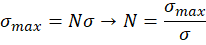
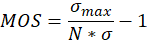
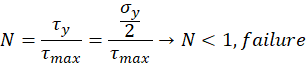
<span> </span>Now that we can find stress, how do we know when a material has failed? A material has failed when the applied stress passes a threshold called the maximum stress or another factor equivalent to maximum stress. This is usually in form of strength ratios/safety factors, <span style="font-size:12pt;line-height:115%;font-family:Aptos, sans-serif;">![embedded-image-uyfld80e.png](https://wiki.ufsolargators.org/uploads/images/gallery/2026-04/embedded-image-uyfld80e.png)</span><span>,</span> (1) with a following margin of safety,<span style="font-size:12pt;line-height:115%;font-family:Aptos, sans-serif;">![embedded-image-1uf9cnrp.png](https://wiki.ufsolargators.org/uploads/images/gallery/2026-04/embedded-image-1uf9cnrp.png)</span><span>,</span> (2). When the strength ratio goes below 1 the material has failed, and how far the factor of safety is to the desired factor of safety can be seen with the margin of safety. Both are expected to be shown for all analysis work.

The Theoretical maximum stress/strength a material can take is one third it’s stiffness (the strength required to split atoms); however, this is far beyond the strength of any material we see. This is due to metals failing from atoms slipping not splitting, and brittle material having large discontinuities, voids, fracturing, and other defects that amplify the stress by large amounts. Ductile materials fail in shear stress and brittle materials fail in normal stress; we can distinguish this by transforming the stress matrix into two constituent forms called the volumetric/hydrostatic stress matrix and the distortional stress matrix. They volumetric stress matrix is defined with hydrostatic stress (2), this matrix does not contribute to ductile failure because ductile failure only occurs from distortional stress. This result of this is brittle materials typically only looking at maximum stress the material can withstand, yield/ultimate stress <span style="font-size:12pt;line-height:115%;font-family:Aptos, sans-serif;">![embedded-image-o7dxmxut.png](https://wiki.ufsolargators.org/uploads/images/gallery/2026-04/embedded-image-o7dxmxut.png)</span><span>, called maximum principal stress failure criteria (5) and ductile materials using maximum shear stress (6) or von-mises/distortional energy (7) failure criteria. </span>

<table class="MsoTableGrid" id="bkmrk-%281%29%C2%A0%C2%A0%C2%A0-%C2%A0-%282%29%C2%A0%C2%A0%C2%A0-%C2%A0-%283" style="width:467.75pt;border-collapse:collapse;border:none;"><tbody><tr><td style="width:418.25pt;padding:0in 5.4pt 0in 5.4pt;"><span style="font-size:12pt;line-height:115%;font-family:Aptos, sans-serif;">![embedded-image-oyckzs9h.png](https://wiki.ufsolargators.org/uploads/images/gallery/2026-04/embedded-image-oyckzs9h.png)</span>

</td><td style="width:49.5pt;padding:0in 5.4pt 0in 5.4pt;"><span><span>(1)<span style="font:7pt 'Times New Roman';"> </span></span></span>

</td></tr><tr><td style="width:418.25pt;padding:0in 5.4pt 0in 5.4pt;"><span style="font-size:12pt;line-height:115%;font-family:Aptos, sans-serif;">![embedded-image-vhkspsg1.png](https://wiki.ufsolargators.org/uploads/images/gallery/2026-04/embedded-image-vhkspsg1.png)</span>

</td><td style="width:49.5pt;padding:0in 5.4pt 0in 5.4pt;"><span><span>(2)<span style="font:7pt 'Times New Roman';"> </span></span></span>

</td></tr><tr><td style="width:418.25pt;padding:0in 5.4pt 0in 5.4pt;"><span style="font-size:12pt;line-height:115%;font-family:Aptos, sans-serif;">![embedded-image-cpd9tepz.png](https://wiki.ufsolargators.org/uploads/images/gallery/2026-04/embedded-image-cpd9tepz.png)</span>

</td><td style="width:49.5pt;padding:0in 5.4pt 0in 5.4pt;"><span><span>(3)<span style="font:7pt 'Times New Roman';"> </span></span></span>

</td></tr><tr><td style="width:418.25pt;padding:0in 5.4pt 0in 5.4pt;"><span style="font-size:12pt;line-height:115%;font-family:Aptos, sans-serif;">![embedded-image-vwdfaflt.png](https://wiki.ufsolargators.org/uploads/images/gallery/2026-04/embedded-image-vwdfaflt.png)</span>

</td><td style="width:49.5pt;padding:0in 5.4pt 0in 5.4pt;"><span><span>(4)<span style="font:7pt 'Times New Roman';"> </span></span></span>

</td></tr><tr><td style="width:418.25pt;padding:0in 5.4pt 0in 5.4pt;"><span style="font-size:12pt;line-height:115%;font-family:Aptos, sans-serif;">![embedded-image-5spfsjyr.png](https://wiki.ufsolargators.org/uploads/images/gallery/2026-04/embedded-image-5spfsjyr.png)</span>

</td><td style="width:49.5pt;padding:0in 5.4pt 0in 5.4pt;"><span><span>(5)<span style="font:7pt 'Times New Roman';"> </span></span></span>

</td></tr><tr><td style="width:418.25pt;padding:0in 5.4pt 0in 5.4pt;"><span style="font-size:12pt;line-height:115%;font-family:Aptos, sans-serif;">![embedded-image-fhont6ts.png](https://wiki.ufsolargators.org/uploads/images/gallery/2026-04/embedded-image-fhont6ts.png)</span>

</td><td style="width:49.5pt;padding:0in 5.4pt 0in 5.4pt;"><span><span>(6)<span style="font:7pt 'Times New Roman';"> </span></span></span>

</td></tr><tr><td style="width:418.25pt;padding:0in 5.4pt 0in 5.4pt;"><span style="font-size:12pt;line-height:115%;font-family:Aptos, sans-serif;">![embedded-image-tn2qnmbi.png](https://wiki.ufsolargators.org/uploads/images/gallery/2026-04/embedded-image-tn2qnmbi.png)</span>

<span style="font-size:12pt;line-height:115%;font-family:Aptos, sans-serif;">![embedded-image-c9x1uty2.png](https://wiki.ufsolargators.org/uploads/images/gallery/2026-04/embedded-image-c9x1uty2.png)</span>

</td><td style="width:49.5pt;padding:0in 5.4pt 0in 5.4pt;"><span><span>(7)<span style="font:7pt 'Times New Roman';"> </span></span></span>

</td></tr></tbody></table>

2\. Composites

working on it

# Material Properties List

Material Properties Sheet Link: [https://docs.google.com/spreadsheets/d/10BFg2Ebkowm6dNkgG27hSjeSBtV-hXoa/edit?usp=sharing&amp;ouid=111074214360211582458&amp;rtpof=true&amp;sd=true](https://docs.google.com/spreadsheets/d/10BFg2Ebkowm6dNkgG27hSjeSBtV-hXoa/edit?usp=sharing&ouid=111074214360211582458&rtpof=true&sd=true)

<table dir="ltr" id="bkmrk-material-units-e1-e2" style="table-layout:fixed;font-size:11pt;font-family:Calibri;width:0px;border-collapse:collapse;border:double rgb(0,0,0);border-spacing:0px;background-color:rgb(255,255,255);"><colgroup><col style="width:162px;"></col><col style="width:82px;"></col><col style="width:76px;"></col><col style="width:76px;"></col><col style="width:76px;"></col><col style="width:60px;"></col><col style="width:60px;"></col><col style="width:60px;"></col><col style="width:60px;"></col><col style="width:60px;"></col><col style="width:60px;"></col><col style="width:67px;"></col><col style="width:60px;"></col><col style="width:647px;"></col></colgroup><tbody><tr style="height:19px;"><td style="overflow:hidden;padding:0px 3px;vertical-align:bottom;border-color:rgb(0,0,0);">Material</td><td style="overflow:hidden;padding:0px 3px;vertical-align:bottom;border-color:rgb(0,0,0);">Units</td><td style="overflow:hidden;padding:0px 3px;vertical-align:bottom;border-color:rgb(0,0,0);">E1</td><td style="overflow:hidden;padding:0px 3px;vertical-align:bottom;border-color:rgb(0,0,0);">E2</td><td style="overflow:hidden;padding:0px 3px;vertical-align:bottom;border-color:rgb(0,0,0);">G12</td><td style="overflow:hidden;padding:0px 3px;vertical-align:bottom;border-color:rgb(0,0,0);">v12</td><td style="overflow:hidden;padding:0px 3px;vertical-align:bottom;border-color:rgb(0,0,0);">t</td><td style="overflow:hidden;padding:0px 3px;vertical-align:bottom;border-color:rgb(0,0,0);">a</td><td style="overflow:hidden;padding:0px 3px;vertical-align:bottom;border-color:rgb(0,0,0);">SL+</td><td style="overflow:hidden;padding:0px 3px;vertical-align:bottom;border-color:rgb(0,0,0);">SL-</td><td style="overflow:hidden;padding:0px 3px;vertical-align:bottom;border-color:rgb(0,0,0);">ST+</td><td style="overflow:hidden;padding:0px 3px;vertical-align:bottom;border-color:rgb(0,0,0);">ST-</td><td style="overflow:hidden;padding:0px 3px;vertical-align:bottom;border-color:rgb(0,0,0);">SS</td><td style="overflow:hidden;padding:0px 3px;vertical-align:bottom;border-color:rgb(0,0,0);">Citation</td></tr><tr style="height:19px;"><td style="overflow:hidden;padding:0px 3px;vertical-align:bottom;border-color:rgb(0,0,0);">T300/8500, vf = .6</td><td style="overflow:hidden;padding:0px 3px;vertical-align:bottom;border-color:rgb(0,0,0);">GPa,mm,Mpa</td><td style="overflow:hidden;padding:0px 3px;vertical-align:bottom;text-align:right;border-color:rgb(0,0,0);">151</td><td style="overflow:hidden;padding:0px 3px;vertical-align:bottom;text-align:right;border-color:rgb(0,0,0);">7.98</td><td style="overflow:hidden;padding:0px 3px;vertical-align:bottom;text-align:right;border-color:rgb(0,0,0);">4.1</td><td style="overflow:hidden;padding:0px 3px;vertical-align:bottom;text-align:right;border-color:rgb(0,0,0);">0.248</td><td style="overflow:hidden;padding:0px 3px;vertical-align:bottom;text-align:right;border-color:rgb(0,0,0);">0.259</td><td style="overflow:hidden;padding:0px 3px;vertical-align:bottom;border-color:rgb(0,0,0);">idk</td><td style="overflow:hidden;padding:0px 3px;vertical-align:bottom;text-align:right;border-color:rgb(0,0,0);">1448</td><td style="overflow:hidden;padding:0px 3px;vertical-align:bottom;text-align:right;border-color:rgb(0,0,0);">1448</td><td style="overflow:hidden;padding:0px 3px;vertical-align:bottom;text-align:right;border-color:rgb(0,0,0);">44.8</td><td style="overflow:hidden;padding:0px 3px;vertical-align:bottom;text-align:right;border-color:rgb(0,0,0);">248</td><td style="overflow:hidden;padding:0px 3px;vertical-align:bottom;text-align:right;border-color:rgb(0,0,0);">62.1</td><td style="overflow:hidden;padding:0px 3px;vertical-align:bottom;border-color:rgb(0,0,0);">*Veloso, Mota, Cunha, "Analytical design of in-plane and through-the-thickness auxetic composite laminates"*</td></tr><tr style="height:19px;"><td style="overflow:hidden;padding:0px 3px;vertical-align:bottom;border-color:rgb(0,0,0);">Kevlar 49, vf = .6</td><td style="overflow:hidden;padding:0px 3px;vertical-align:bottom;border-color:rgb(0,0,0);">GPa,mm,MPa</td><td style="overflow:hidden;padding:0px 3px;vertical-align:bottom;text-align:right;border-color:rgb(0,0,0);">112.4</td><td style="overflow:hidden;padding:0px 3px;vertical-align:bottom;text-align:right;border-color:rgb(0,0,0);">4.48</td><td style="overflow:hidden;padding:0px 3px;vertical-align:bottom;text-align:right;border-color:rgb(0,0,0);">2.57</td><td style="overflow:hidden;padding:0px 3px;vertical-align:bottom;text-align:right;border-color:rgb(0,0,0);">0.36</td><td style="overflow:hidden;padding:0px 3px;vertical-align:bottom;text-align:right;border-color:rgb(0,0,0);">0.29</td><td style="overflow:hidden;padding:0px 3px;vertical-align:bottom;border-color:rgb(0,0,0);">idk</td><td style="overflow:hidden;padding:0px 3px;vertical-align:bottom;text-align:right;border-color:rgb(0,0,0);">1379</td><td style="overflow:hidden;padding:0px 3px;vertical-align:bottom;text-align:right;border-color:rgb(0,0,0);">276</td><td style="overflow:hidden;padding:0px 3px;vertical-align:bottom;text-align:right;border-color:rgb(0,0,0);">27.6</td><td style="overflow:hidden;padding:0px 3px;vertical-align:bottom;text-align:right;border-color:rgb(0,0,0);">64.8</td><td style="overflow:hidden;padding:0px 3px;vertical-align:bottom;text-align:right;border-color:rgb(0,0,0);">60.0</td><td style="overflow:hidden;padding:0px 3px;vertical-align:bottom;border-color:rgb(0,0,0);">*Gibson, "Principles of Composite Material Mechanics"*</td></tr><tr style="height:19px;"><td style="overflow:hidden;padding:0px 3px;vertical-align:bottom;border-color:rgb(0,0,0);">E-glass/8500, vf = .6</td><td style="overflow:hidden;padding:0px 3px;vertical-align:bottom;border-color:rgb(0,0,0);">GPa,mm,MPa</td><td style="overflow:hidden;padding:0px 3px;vertical-align:bottom;text-align:right;border-color:rgb(0,0,0);">45.7</td><td style="overflow:hidden;padding:0px 3px;vertical-align:bottom;text-align:right;border-color:rgb(0,0,0);">10.5</td><td style="overflow:hidden;padding:0px 3px;vertical-align:bottom;text-align:right;border-color:rgb(0,0,0);">4.1</td><td style="overflow:hidden;padding:0px 3px;vertical-align:bottom;text-align:right;border-color:rgb(0,0,0);">0.252</td><td style="overflow:hidden;padding:0px 3px;vertical-align:bottom;text-align:right;border-color:rgb(0,0,0);">0.208</td><td style="overflow:hidden;padding:0px 3px;vertical-align:bottom;border-color:rgb(0,0,0);">idk</td><td style="overflow:hidden;padding:0px 3px;vertical-align:bottom;text-align:right;border-color:rgb(0,0,0);">584</td><td style="overflow:hidden;padding:0px 3px;vertical-align:bottom;text-align:right;border-color:rgb(0,0,0);">803</td><td style="overflow:hidden;padding:0px 3px;vertical-align:bottom;text-align:right;border-color:rgb(0,0,0);">43</td><td style="overflow:hidden;padding:0px 3px;vertical-align:bottom;text-align:right;border-color:rgb(0,0,0);">187</td><td style="overflow:hidden;padding:0px 3px;vertical-align:bottom;text-align:right;border-color:rgb(0,0,0);">64</td><td style="overflow:hidden;padding:0px 3px;vertical-align:bottom;border-color:rgb(0,0,0);">*Veloso, Mota, Cunha, "Analytical design of in-plane and through-the-thickness auxetic composite laminates"*</td></tr><tr style="height:19px;"><td style="overflow:hidden;padding:0px 3px;vertical-align:bottom;border-color:rgb(0,0,0);">IM7/977-3</td><td style="overflow:hidden;padding:0px 3px;vertical-align:bottom;border-color:rgb(0,0,0);">GPa,mm,GPa</td><td style="overflow:hidden;padding:0px 3px;vertical-align:bottom;text-align:right;border-color:rgb(0,0,0);">191</td><td style="overflow:hidden;padding:0px 3px;vertical-align:bottom;text-align:right;border-color:rgb(0,0,0);">9.94</td><td style="overflow:hidden;padding:0px 3px;vertical-align:bottom;text-align:right;border-color:rgb(0,0,0);">7.79</td><td style="overflow:hidden;padding:0px 3px;vertical-align:bottom;text-align:right;border-color:rgb(0,0,0);">0.35</td><td style="overflow:hidden;padding:0px 3px;vertical-align:bottom;text-align:right;border-color:rgb(0,0,0);">0.259</td><td style="overflow:hidden;padding:0px 3px;vertical-align:bottom;border-color:rgb(0,0,0);">idk</td><td style="overflow:hidden;padding:0px 3px;vertical-align:bottom;text-align:right;border-color:rgb(0,0,0);">3.25</td><td style="overflow:hidden;padding:0px 3px;vertical-align:bottom;text-align:right;border-color:rgb(0,0,0);">1.6</td><td style="overflow:hidden;padding:0px 3px;vertical-align:bottom;text-align:right;border-color:rgb(0,0,0);">0.062</td><td style="overflow:hidden;padding:0px 3px;vertical-align:bottom;text-align:right;border-color:rgb(0,0,0);">0.098</td><td style="overflow:hidden;padding:0px 3px;vertical-align:bottom;text-align:right;border-color:rgb(0,0,0);">0.075</td><td style="overflow:hidden;padding:0px 3px;vertical-align:bottom;border-color:rgb(0,0,0);">*Tsai, Melo, "An invariant-based theory of composites"*</td></tr><tr style="height:19px;"><td style="overflow:hidden;padding:0px 3px;vertical-align:bottom;border-color:rgb(0,0,0);">T700 C-Ply 55</td><td style="overflow:hidden;padding:0px 3px;vertical-align:bottom;border-color:rgb(0,0,0);">GPa,mm,GPa</td><td style="overflow:hidden;padding:0px 3px;vertical-align:bottom;text-align:right;border-color:rgb(0,0,0);">121</td><td style="overflow:hidden;padding:0px 3px;vertical-align:bottom;text-align:right;border-color:rgb(0,0,0);">8</td><td style="overflow:hidden;padding:0px 3px;vertical-align:bottom;text-align:right;border-color:rgb(0,0,0);">4.7</td><td style="overflow:hidden;padding:0px 3px;vertical-align:bottom;text-align:right;border-color:rgb(0,0,0);">0.3</td><td style="overflow:hidden;padding:0px 3px;vertical-align:bottom;text-align:right;border-color:rgb(0,0,0);">0.259</td><td style="overflow:hidden;padding:0px 3px;vertical-align:bottom;border-color:rgb(0,0,0);">idk</td><td style="overflow:hidden;padding:0px 3px;vertical-align:bottom;text-align:right;border-color:rgb(0,0,0);">2.53</td><td style="overflow:hidden;padding:0px 3px;vertical-align:bottom;text-align:right;border-color:rgb(0,0,0);">1.7</td><td style="overflow:hidden;padding:0px 3px;vertical-align:bottom;text-align:right;border-color:rgb(0,0,0);">0.066</td><td style="overflow:hidden;padding:0px 3px;vertical-align:bottom;text-align:right;border-color:rgb(0,0,0);">0.022</td><td style="overflow:hidden;padding:0px 3px;vertical-align:bottom;text-align:right;border-color:rgb(0,0,0);">0.093</td><td style="overflow:hidden;padding:0px 3px;vertical-align:bottom;border-color:rgb(0,0,0);">*Tsai, Melo, "An invariant-based theory of composites"*</td></tr><tr style="height:19px;"><td style="overflow:hidden;padding:0px 3px;vertical-align:bottom;border-color:rgb(0,0,0);">T800/Cytec</td><td style="overflow:hidden;padding:0px 3px;vertical-align:bottom;border-color:rgb(0,0,0);">Gpa,mm,Gpa</td><td style="overflow:hidden;padding:0px 3px;vertical-align:bottom;text-align:right;border-color:rgb(0,0,0);">162</td><td style="overflow:hidden;padding:0px 3px;vertical-align:bottom;text-align:right;border-color:rgb(0,0,0);">9</td><td style="overflow:hidden;padding:0px 3px;vertical-align:bottom;text-align:right;border-color:rgb(0,0,0);">5</td><td style="overflow:hidden;padding:0px 3px;vertical-align:bottom;text-align:right;border-color:rgb(0,0,0);">0.4</td><td style="overflow:hidden;padding:0px 3px;vertical-align:bottom;text-align:right;border-color:rgb(0,0,0);">0.259</td><td style="overflow:hidden;padding:0px 3px;vertical-align:bottom;border-color:rgb(0,0,0);">idk</td><td style="overflow:hidden;padding:0px 3px;vertical-align:bottom;text-align:right;border-color:rgb(0,0,0);">3.77</td><td style="overflow:hidden;padding:0px 3px;vertical-align:bottom;text-align:right;border-color:rgb(0,0,0);">1.66</td><td style="overflow:hidden;padding:0px 3px;vertical-align:bottom;text-align:right;border-color:rgb(0,0,0);">0.056</td><td style="overflow:hidden;padding:0px 3px;vertical-align:bottom;text-align:right;border-color:rgb(0,0,0);">0.15</td><td style="overflow:hidden;padding:0px 3px;vertical-align:bottom;text-align:right;border-color:rgb(0,0,0);">0.098</td><td style="overflow:hidden;padding:0px 3px;vertical-align:bottom;border-color:rgb(0,0,0);">*Tsai, Melo, "An invariant-based theory of composites"*</td></tr><tr style="height:19px;"><td style="overflow:hidden;padding:0px 3px;vertical-align:bottom;border-color:rgb(0,0,0);">Woven 2024-2025 Chassis</td><td style="overflow:hidden;padding:0px 3px;vertical-align:bottom;border-color:rgb(0,0,0);">Pa,mm,Pa</td><td style="overflow:hidden;padding:0px 3px;vertical-align:bottom;text-align:right;border-color:rgb(0,0,0);">5.20E+10</td><td style="overflow:hidden;padding:0px 3px;vertical-align:bottom;text-align:right;border-color:rgb(0,0,0);">5.20E+10</td><td style="overflow:hidden;padding:0px 3px;vertical-align:bottom;text-align:right;border-color:rgb(0,0,0);">2.90E+09</td><td style="overflow:hidden;padding:0px 3px;vertical-align:bottom;text-align:right;border-color:rgb(0,0,0);">0.04</td><td style="overflow:hidden;padding:0px 3px;vertical-align:bottom;text-align:right;border-color:rgb(0,0,0);">0.259</td><td style="overflow:hidden;padding:0px 3px;vertical-align:bottom;border-color:rgb(0,0,0);">idk</td><td style="overflow:hidden;padding:0px 3px;vertical-align:bottom;text-align:right;border-color:rgb(0,0,0);">5.13E+08</td><td style="overflow:hidden;padding:0px 3px;vertical-align:bottom;text-align:right;border-color:rgb(0,0,0);">-4.37E+08</td><td style="overflow:hidden;padding:0px 3px;vertical-align:bottom;text-align:right;border-color:rgb(0,0,0);">5.13E+08</td><td style="overflow:hidden;padding:0px 3px;vertical-align:bottom;text-align:right;border-color:rgb(0,0,0);">-4.37E+08</td><td style="overflow:hidden;padding:0px 3px;vertical-align:bottom;text-align:right;border-color:rgb(0,0,0);">1.20E+08</td><td style="overflow:hidden;padding:0px 3px;vertical-align:bottom;border-color:rgb(0,0,0);">*2025 VDR - Kurt Portfolio*</td></tr></tbody></table>

# Composite First Principles

<span style="text-decoration:underline;">**This page does not go over classical laminate theory or anything past first order analysis of composites.**</span>

### Intro:

Composite materials are core to how we make lightweight long term parts on the car. At a fundamental level, composite materials are what they sound like, mixed materials. This comes mixed mechanical behavior and varying failure modes not typical of homogenous materials.

- Modulus of elasticity: for softer materials, lower modulus materials, will have less stress than those of hard materials. Loads through composite material have constant (membrane) or linear (bending) strain/loads, but the associated stress varies with stiffness.
- Poissons ratio (dilation effects): the primary concern for debonding the two materials
- Strength: materials can break resulting a nonlinear stress-strain curve
- Failure modes: debonding becomes a failure mode.

[![image.png](https://wiki.ufsolargators.org/uploads/images/gallery/2026-08/scaled-1680-/image.png)](https://wiki.ufsolargators.org/uploads/images/gallery/2026-08/image.png)[![image.png](https://wiki.ufsolargators.org/uploads/images/gallery/2026-08/scaled-1680-/8gximage.png)](https://wiki.ufsolargators.org/uploads/images/gallery/2026-08/8gximage.png)

The choice to use composites over metallic components is a common debate and usually comes down a couple issues with composites:

Pros:

- Very low weight for how strong it is
- Can behave as rigid bodies due to psudo-brittle behavior
- Complex mechanical behavior can allow for high amounts of customized behavior
- Can be used for "quick" repair of parts

Con:

- Complex failure modes
- Loads should be specific
- Manufacturing is unconventional and sometimes difficult to replicate expected behavior
- Behavior is complex and hard to define
- First principles are hard to integrate well and not taught much in school

This page will go over how to think, design, analyze, and manufacture with composites.

#### Think:

Traditional composites are more common in civil engineering, think concrete and rebar. Our club primarily does polymer composite work with thin glass, kevlar, or carbon fiber, which are more common in mechanical/aerospace applications. "Composites" will from now on be in reference to GFRP or CFRP, glass fiber reignforced polymer or carbon fiber reignforced polymer. The two components of composites are the fibre and matrix, the fibre contains the material strength and the matrix is the medium that the load is exchanged. The matrix is usually a elastic polymer and fibre is usually a brittle glass or graphite. Another way to think about it is, graphite fibre lack transverse strength that make them break immediatly upon off-axis loads that gets compenated for by the matrix, this can be seen in the figure below. The fibre generates most of the modulus and strength, the matrix accounts to off-axis loading.

[![image.png](https://wiki.ufsolargators.org/uploads/images/gallery/2026-08/scaled-1680-/kanimage.png)](https://wiki.ufsolargators.org/uploads/images/gallery/2026-08/kanimage.png)

For a uni-directional fabric, fabric where the fibre only go in one direction, 88.5% of the total potential stiffness is in the longitudinal/fibre direction, 5.25% in the transverse direction, and 1.6% is shear stiffness. These charactertics follow with textiles fabrics, plain weave is 44.5% for longitudinal and transverse directions.

**Uni vs Textile:** The stiffness carbon fiber is some variation of sinusoidal, with longitudinal stiffness of a unidirectional fabric decribed by Q11=A+B\*cos(2theta)+C\*cos(4theta). This discrepancy between 2theta and 4theta can be transfered into mohr space to depict stiffness within 2 seperate circles. THIS IS ONLY RELEVANT FOR UNIDIRECTIONAL FABRIC, and leads to intense deformation coupling behavior if not careful. This coupling behavior can get complicated and will be descirbed later, but bi-directional/textile fabrics negate this inclination by removing the 2theta's singificance. Tldr, uni-directional fabric is less stable than textiles; resulting in only having two primary directions (on-axis and off-axis), in practice. Textile fabrics also will stop prolong cracking that can occur in unidirectional fabric; the cracks that begin in unidirectional fabric have to keep going vs textile that will stop due to the other transverse fabric being there. Uni-directional fabric and textile fabrics seem to still homogenize similarly, with textiles sometimes homogenizing faster, so be carful about using off-axis directions.

[![image.png](https://wiki.ufsolargators.org/uploads/images/gallery/2026-08/scaled-1680-/d3Qimage.png)](https://wiki.ufsolargators.org/uploads/images/gallery/2026-08/d3Qimage.png)

[![image.png](https://wiki.ufsolargators.org/uploads/images/gallery/2026-08/scaled-1680-/cZdimage.png)](https://wiki.ufsolargators.org/uploads/images/gallery/2026-08/cZdimage.png)

[![image.png](https://wiki.ufsolargators.org/uploads/images/gallery/2026-08/scaled-1680-/B4kimage.png)](https://wiki.ufsolargators.org/uploads/images/gallery/2026-08/B4kimage.png)[![image.png](https://wiki.ufsolargators.org/uploads/images/gallery/2026-08/scaled-1680-/MSGimage.png)](https://wiki.ufsolargators.org/uploads/images/gallery/2026-08/MSGimage.png)

### First-Principles:

##### Basics:

These are the first-order principles to give some basis of understanding for how to work with and talk about composites.

Fibre reinforced polymers are used for in-plane tensile and bending loads. Out-of-plane loads are compensated by core, typically. The combination of core and facesheet are called "Sandwich Panels." F<span class="TermText notranslate lang-en">ace sheet carrys all inplane loads (A &amp; D), while the core provides shear continunity, so sandwich acts as unit for reisting bending loads (both faces act together). The most common fibres, matrices, and cores are seen below.</span>

Common fibres include:

- Carbon - common for structural applications. Stiffness can vary between grades. T300 is the lowest stiffness grade and T1000 is the highest, higher stiffness does not mean stronger. Comes in uni-directional and textile fabrics. Textiles include plain weave, twill, satin, and a bunch of other ones. Carbon is graphite and is on the opposite side of the galvanic chart to aluminum, corrodes alumnimum and needs either glass, paint, or some film to prevent corrosion.
- E-glass - used in PCBs and for higher strain loads. It's cheaper and heavier than carbon. It can be dyed to change color and is clear when laminated. Commonly used over fillets for increased strength, minimal stiffness, and clear to see if cracks are forming. It is called soft due to it's lower modulus, not a bad characteristic.
- S-glass - structural glass fibre used for structural applications when carbon can't be used. Great for fillet where E-glass can't. Does not corrode with aluminum.
- Kevlar - only for structural application in tension, doesn't conduct heat, but is expensive and horrible to cut. Avoid if possible.

Common matrices include:

- Epoxy - Most common matrix used. Common for structural loads, breaks like glass but is very elastic. Clear so it can be dyed. There are high thermal variates. Does not have much warpage, making it the easiest to use. Expensive depending on the seller and purpose.
- Polyester - Common for mold use due to it being cheap. High degrees of warpage and is very weak. Do not use for structures.
- Phenolic - Common for high heat use. Releases a gas film when heated up that prevents heat transfer from irradiation. Do not use for solar car, only used for space stuff sometimes.

Common textile farbic forms include:

- Plain weave is the easiest to model and think about, but can be hard to drap along large curvatures for molds. Can be slightly more expensive than twill.
- Twill is the cheapest variant and acts the same as plain weave in macro-scale, but is hard to model in meso-scale. Easy to drap over large curvatures. Probably the most common fabric used.
- Satin is a weird one that used primarily for very specific curvatures, can be very difficult to model in meso-scale, but is do-able.

[![image.png](https://wiki.ufsolargators.org/uploads/images/gallery/2026-08/scaled-1680-/g7Pimage.png)](https://wiki.ufsolargators.org/uploads/images/gallery/2026-08/g7Pimage.png)

Common Cores include:

- Aramid Honeycomb (Nomex) - Lightweight and stiff, common for structural application. Can be hard to bend around curves, so usually requires slits to slide to make a bend. The honeycomb is not the same in both directions, one direction is more compliant than the other, has a sort of auextic behavior.
- Alumnimum Honeycomb - Lightweight and stiff, common for structural application. Easy to bend around curves. Susceptible to corrosion.
- Divinycell (Foam) - Lightweight and mildy stiff, common for suplemental structural application. Can come with slits for infusion, resin flow. Should be worried about epoxy being sucked into the core too much when manufacturing.
- Rohacell (Foam) - Lightweight and stiffer than Divinycell, common for structural application. Sort of stat buffed Divinycell.
- Wood - It's used, but not often. Can be heavy, but is valid when desperate. Very strong and heavy.
- Plastic Honeycomb - Cheap and is core when desperate.

##### Sandwich Panels:

Normal stress is assumed to occur in the facesheets only and uniform across thickness. Shear stress is assumed to occur only in core and uniform in the core. Pros and cons for sandwich panels are:

Pros:

- Very light weight
- Verty high flextural rigidity
- Geat thermal insulation

Cons:

- No acoustic insulation
- Fire resistence not good
- buckling sucks. Compression reistence is limited by ciritical values, which depends on how the type of load determining buckling mode.

Facesheet failure modes include:

- Tension - rupture from tension and bending

[![image.png](https://wiki.ufsolargators.org/uploads/images/gallery/2026-08/scaled-1680-/QXiimage.png)](https://wiki.ufsolargators.org/uploads/images/gallery/2026-08/QXiimage.png)

- Compression - delamination or buckle wrinkling

[![image.png](https://wiki.ufsolargators.org/uploads/images/gallery/2026-08/scaled-1680-/xHSimage.png)](https://wiki.ufsolargators.org/uploads/images/gallery/2026-08/xHSimage.png)

- Shear - delamination

[![image.png](https://wiki.ufsolargators.org/uploads/images/gallery/2026-08/scaled-1680-/REYimage.png)](https://wiki.ufsolargators.org/uploads/images/gallery/2026-08/REYimage.png)

Sandwich panel failure modes include, the ones in bold are the ones I see the most often:

- Facesheet ultimate strength - face sheet yields tension

[![image.png](https://wiki.ufsolargators.org/uploads/images/gallery/2026-08/scaled-1680-/U0Iimage.png)](https://wiki.ufsolargators.org/uploads/images/gallery/2026-08/U0Iimage.png)

- Bending stress -face sheet yields bending
- **Shear crimpling** - local failure, caused by low density core, abrupt shear failure from axial buckling load (load basis)

[![image.png](https://wiki.ufsolargators.org/uploads/images/gallery/2026-08/scaled-1680-/daLimage.png)](https://wiki.ufsolargators.org/uploads/images/gallery/2026-08/daLimage.png)

- **Facesheet wrinkling** - local, low bending stiffness of facesheet and core, higher stiffness increases buckling mode. characterized by depression or debonding in facesheet (stress basis).

[![image.png](https://wiki.ufsolargators.org/uploads/images/gallery/2026-08/scaled-1680-/fwoimage.png)](https://wiki.ufsolargators.org/uploads/images/gallery/2026-08/fwoimage.png)

- Facesheet dimpling - local, influenced by bending stiffness of facesheet relative to unsupported dimension. Only honeycomb, characterized by dimpling (stress basis).
- Column buckling - euler buckling, covers alot of the failure modes but general buckling also occurs. Occurs from non-sufficient bending stiffness, D. First-order view is EI = Db, flextural stiffness = bending stiffness \* thickness. Where the critical load is k\*pi^2\*(Db/L^2)
- Core shear strength - Core shear stress failure

[![image.png](https://wiki.ufsolargators.org/uploads/images/gallery/2026-08/scaled-1680-/WC0image.png)](https://wiki.ufsolargators.org/uploads/images/gallery/2026-08/WC0image.png)

- **Core crush** - point load across a surface area, progressive but can feel sudden. F = P/A, where A is the surface area of contact. It's more of an avalanching crush of the core.
- **Core punch-thru** - shear strength in a perimeter is not adequate. F = P/A, where A is the area around the point load. Punch thru is a sudden drop, more like a hole in the ground than an avalanche.

Core crushing typically occurs with elastic deformantion then progressive uniform crimpling until 70% of the original height is met. At this stage the core has failed but energy is still capable of being absorbed.

[![image.png](https://wiki.ufsolargators.org/uploads/images/gallery/2026-08/scaled-1680-/Ztdimage.png)](https://wiki.ufsolargators.org/uploads/images/gallery/2026-08/Ztdimage.png)

##### Vibations in Honeycomb:

<div class="sm8axow" id="bkmrk-low-hz-%28%3C50-hz%29---be"><div class="s1fbb24p"><div class="h5swuer hnjn0lb">- <span class="TermText notranslate lang-en">low hz (&lt;50 Hz) - bending is uniform</span>
- <span class="TermText notranslate lang-en">mid hz (50-1000 Hz) - transverse shear strain in core</span>
- <span class="TermText notranslate lang-en">high hz (1000+ Hz) - skin bending acts as if disconnected</span>

</div></div></div>##### <span class="TermText notranslate lang-en">Bolts:</span>

<span class="TermText notranslate lang-en">Holes in panels introduces weakening of fracture resistence of 40-60% in tension and 15% in compression. General rules of thumb if hole is failing:</span>

<div class="sm8axow" id="bkmrk-tensile-hole-failure"><div class="s1fbb24p"><div class="h5swuer hnjn0lb">- <span class="TermText notranslate lang-en">Tensile hole failure - insufficient number of 0 deg plies.</span>
- <span class="TermText notranslate lang-en">Shear hole failure - insufficient number of 45 deg plies.</span>
- <span class="TermText notranslate lang-en">Bearing hole failure - insufficient thickness.</span>

</div></div></div><span class="TermText notranslate lang-en">Bearing due to lateral loads is the contact pressure between shaft of bolt and wall; leads to mushrooming and delamination. The resistence of a hole with a bolt is 40% weaker than of empty. Equivalent bearing pressure which leads to crushed walls of hole diameter, d, is F/(d\*e) &lt;= admissible stress which is 500 MPa for CFRP. Stress about holes becomes concentrated which magnifies the nominal stress, this stress is depicted using magnified stress formulas.</span>

- <span class="TermText notranslate lang-en">2\*d distance from free edge</span>
- <span class="TermText notranslate lang-en">4\*d &lt;= pitch &lt;= 6\*d</span>
- <span class="TermText notranslate lang-en">foot &gt;= 6\*d</span>
- <span class="TermText notranslate lang-en">e &gt;= d/2</span>
- <span class="TermText notranslate lang-en">reinforcement at 45 deg recommended</span>

Bolts are subjected to 2 simple loads: bending &amp; shear:

1. Tightening of the bolt will lead to a transmission of contact pressure between the support component &amp; the facing.
2. ΣF will balance out shear load &amp; suppress the risk of face separation.
3. The facing is fragile &amp; cannot permit high contact pressures that are localized under the bolt head &amp; nut, use washers.
4. Bolts accompanied by bonding provide a gain of mechanical performance of 20–30%. At the expense of higher weight.

For bonded joints:

- Avoid tension at all cost.
- Joints must work in shear, in-plane.

[![image.png](https://wiki.ufsolargators.org/uploads/images/gallery/2026-08/scaled-1680-/edmimage.png)](https://wiki.ufsolargators.org/uploads/images/gallery/2026-08/edmimage.png)

[![image.png](https://wiki.ufsolargators.org/uploads/images/gallery/2026-08/scaled-1680-/3pFimage.png)](https://wiki.ufsolargators.org/uploads/images/gallery/2026-08/3pFimage.png)