
Fairing Templates
Fairing templates allow for positioning of the fairing layup before the rest of the bottom body is manufactured. There are multiple ways to approach this The following is how it was performed on car 4
The car 4 bottom body mold does not include the nose. This is advantageous for positioning within the body, as it gives a datum to measure off of. We used this to find the position of the front and rear "axles" of the vehicle, and positioned midpoint of the fairings with the axles on the sides of the mold.
To make the templates, you can use flatten surface feature in solidworks. This requires selecting a group of faces and then a line to base the flatten off of. Think of this process the same way the world map is made, where the equator is the line chosen. The consequence of this is that the further from the line your faces are, with greater curves comes greater distortion (just like Greenland on the world map). You will have an especially hard time fitting flat paper back along those curves when you position them in the mold.
For car 4 a split line was added across the middle face of the fairing, and then flattened along that line. See figures 1 and 2 for examples.
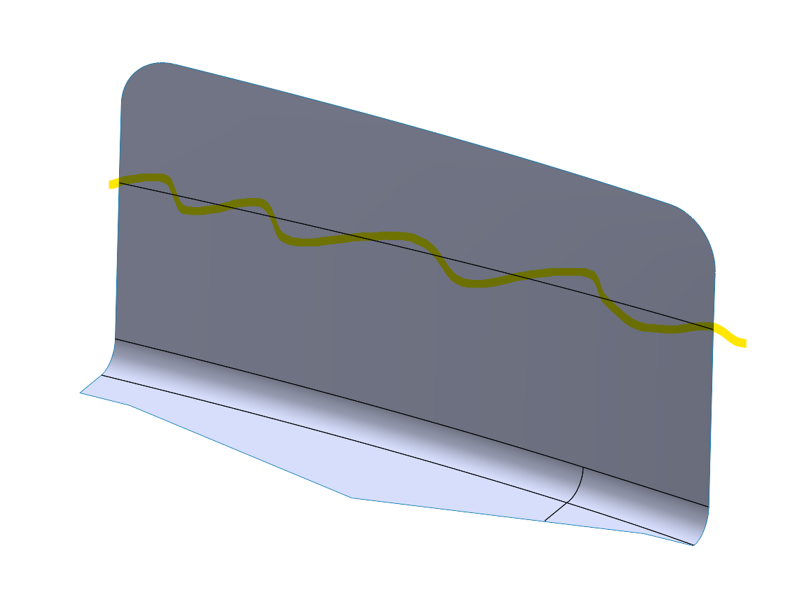 Fig 1. Front fairing with a split line added in the middle (yellow) of the face to give the most accurate flatten geometry
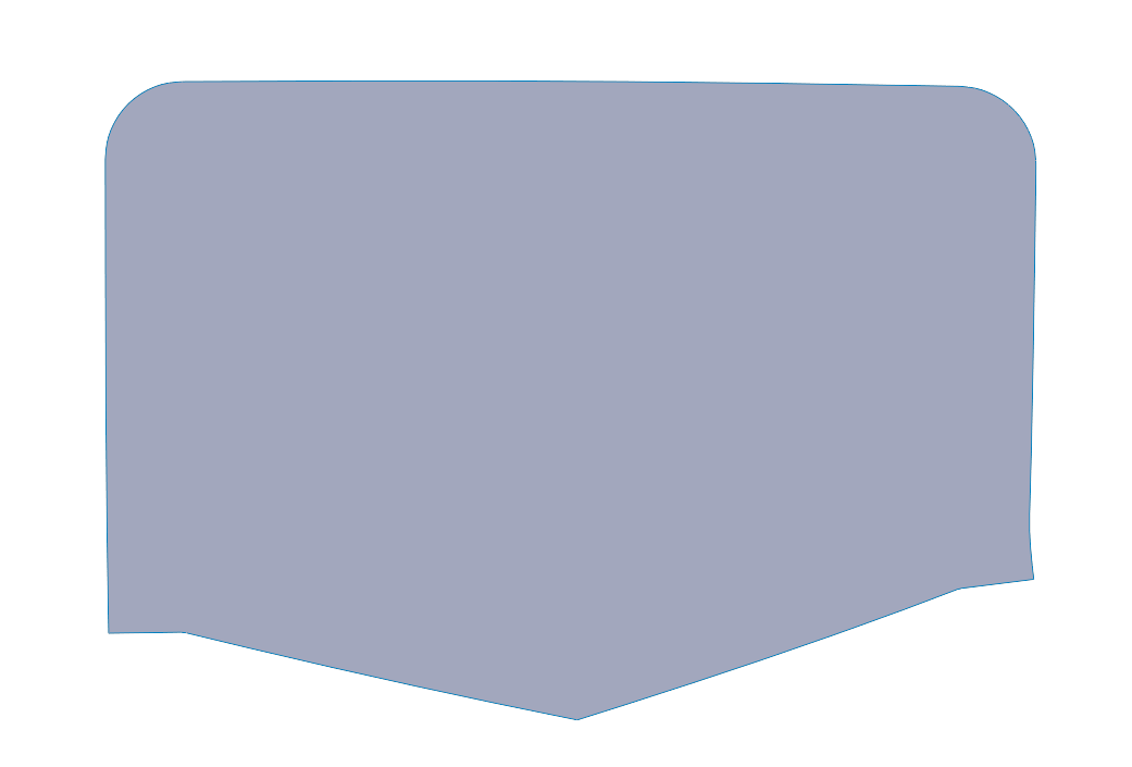
Fig 2. Front fairing when flattened. There is minor distortion on the bottom fillet area
It is beneficial to also have alignment lines on the fairing for knowing roughly where the fillet is, where the midpoint is, and where the wheel will roughly be. These can be achieved through using sketches and then split line features on the face of the flattened geometry. While it is all one face, the line segments are still separate on the sides. We use coincident relations with straight lines to get a rough approximation. One thing to note is that the midpoint line is not necessarily a vertical line here, it is typically at a slight angle. You should look at the CAD of the entire aeroshell to decide how to define it.
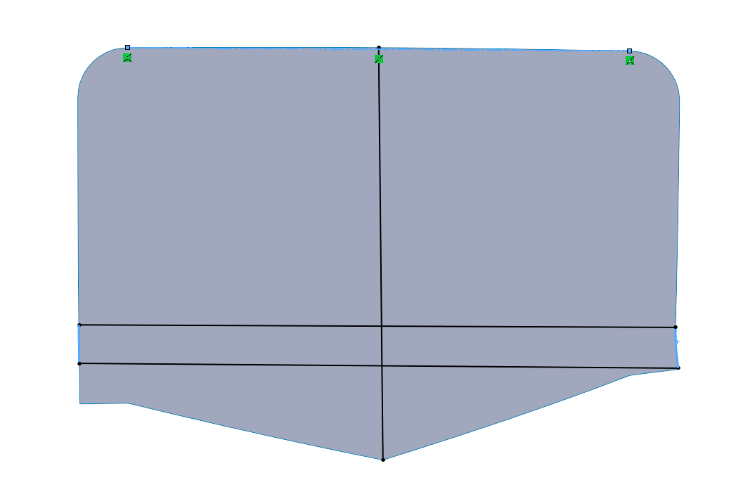
Fig 3. Front fairing split line sketch. Note where the horizonal lines have coincident relations with the line segments on the bottom left and right side of the sketch
There are a couple options for printing. If poster paper is available, you can turn the part into a drawing and save it as a PDF. Do not take a screenshot and have it printed to scale. It will come out super low resolution, you must save it as some sort of scalable vector file type (pdf, svg, etc).
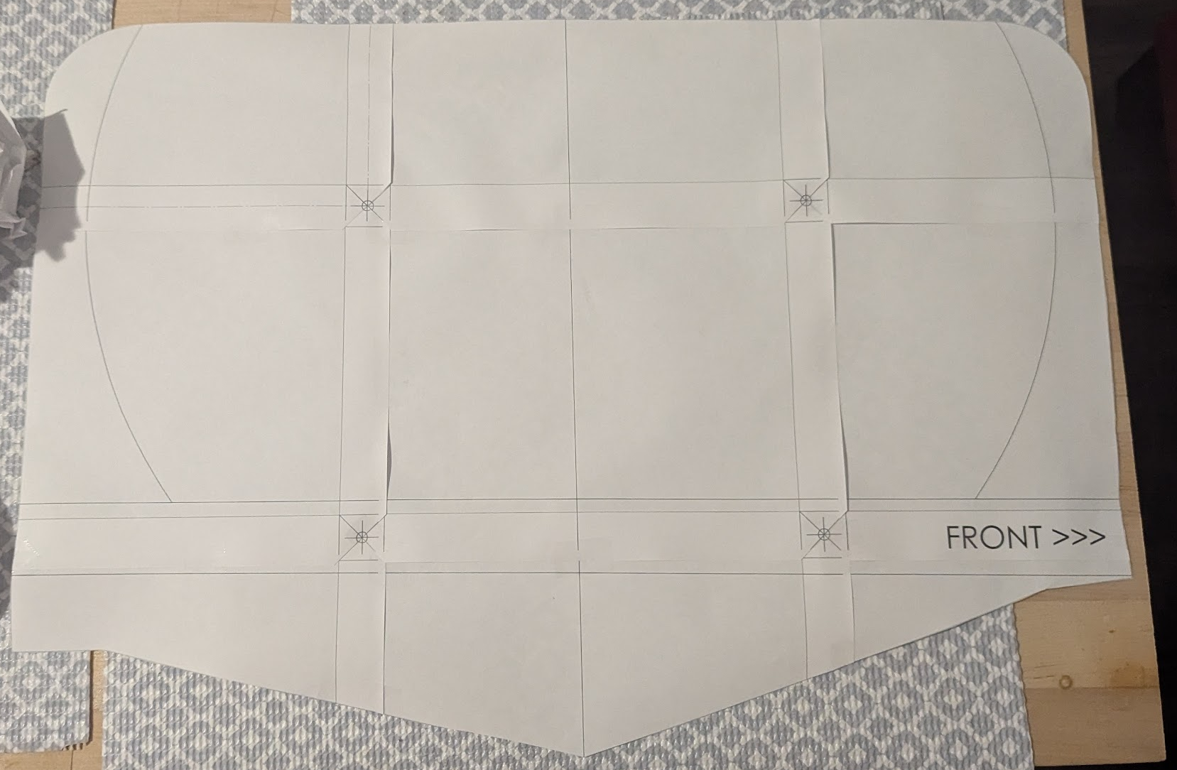
Otherwise, you can do it on a regular printer, sewing template style. Just add a sketch in as the following images show, then use linear pattern it across the part. Make sure to unhide the sketch in both the part and the drawing in order to get it to appear when you save it as a PDF.
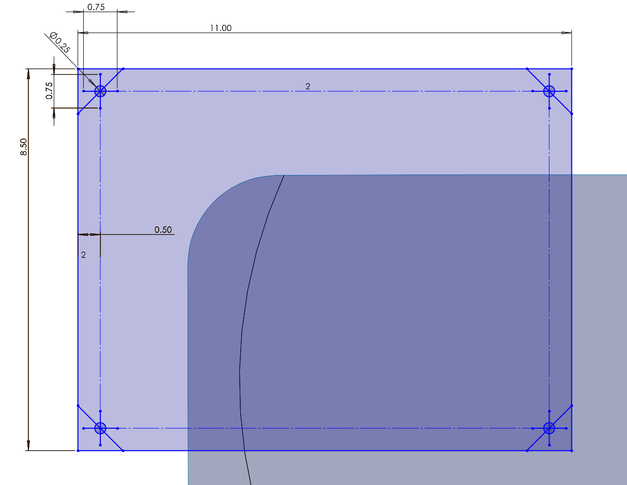
Fig 4. Initial sketch. The big rectangle is the size of a piece of regular paper. The circle/crosshair pieces are for alignment, and the diagonal line in the corners gets cut off on every sheet so that you can align the corners from piece to piece
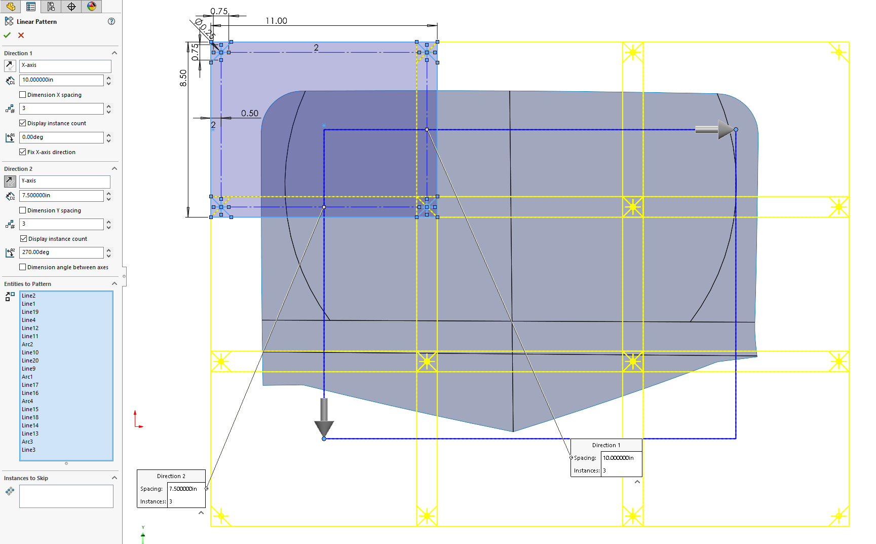
Fig 5. Pattern it across the part at 1 inch less per instance than the size of paper (for copy paper, 10" in x and 7.5" in y)
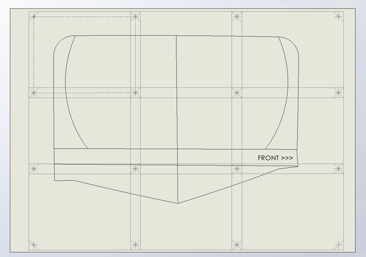
Fig 6. Make sure you can see the sketch in the drawing and save the drawing file as a PDF
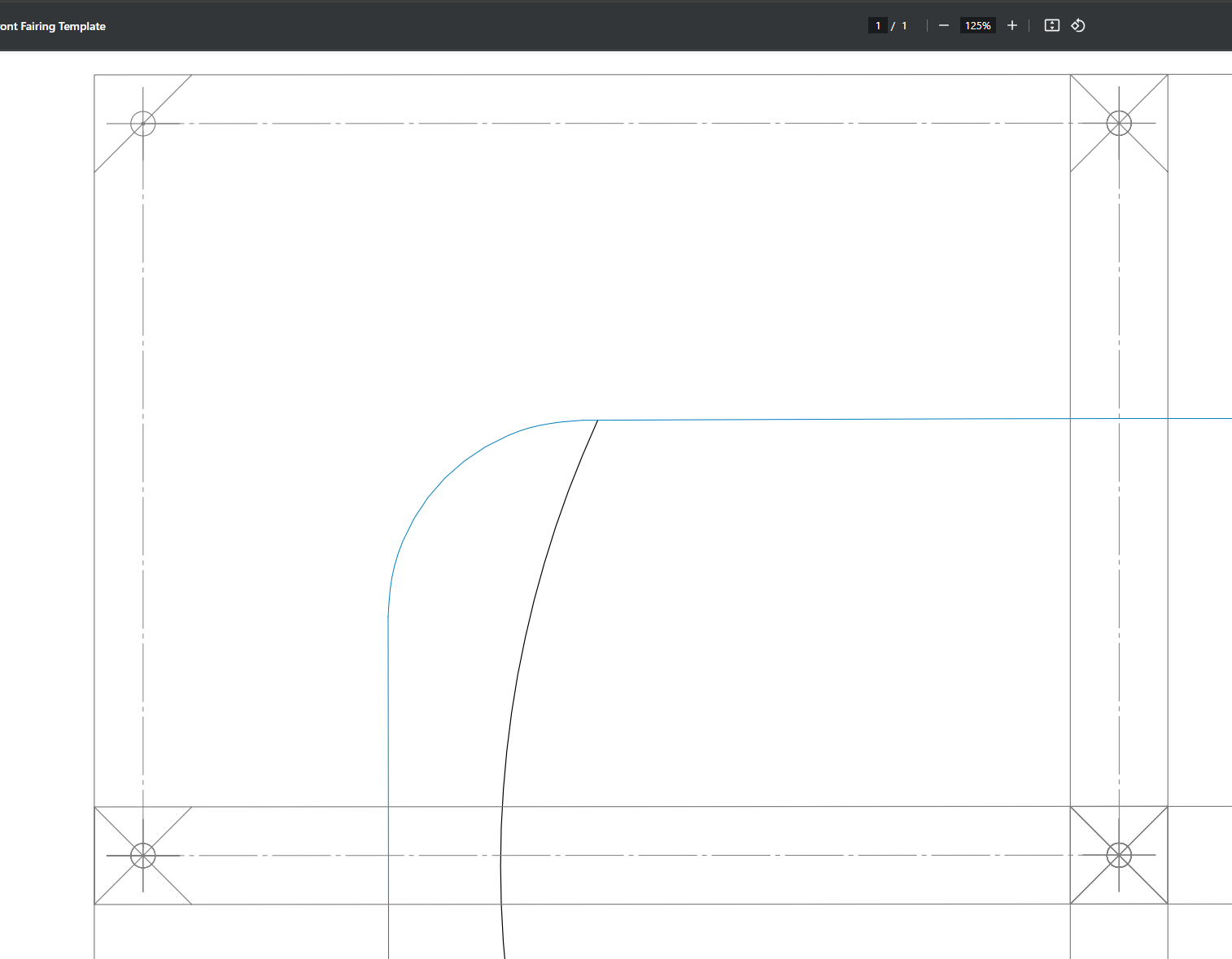
Fig 7. Open the PDF and zoom in on each section one by one and take a screenshot of each, and position each on into a word document with the edges of the rectangle sketch taking up the entire page
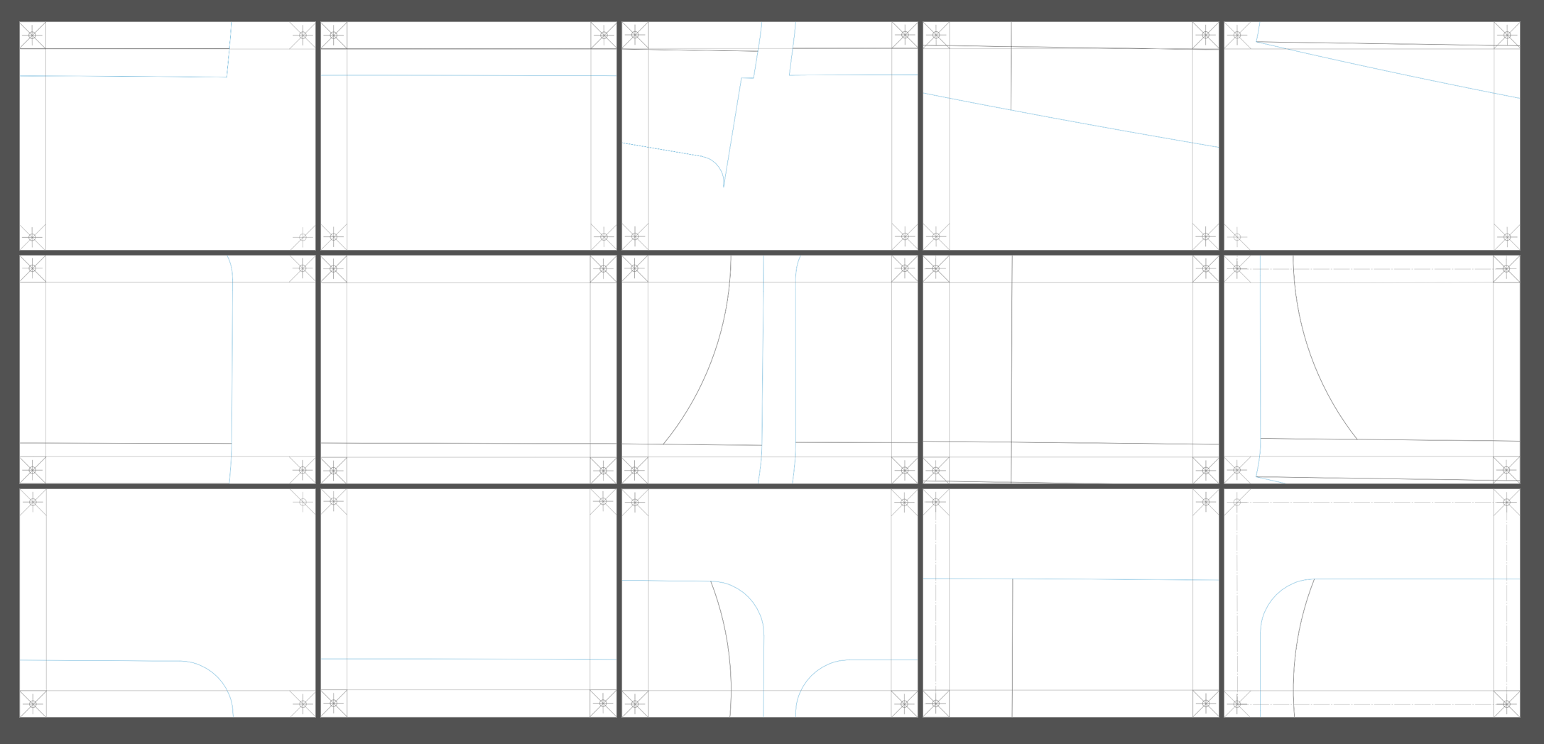
Fig 8. Save this as a PDF now, print, and assemble by cutting off the corners, aligning, and taping together
No comments to display
No comments to display