
Properly Fastened Fairings
Jacalyn Dean, Luke Penafiel
Fairing fasteners refer to the modes in which fairings are fastened to the aerobody of the solar car. While simple in design, the results of different designs can prove crucial during the extreme environment of competition. During competition, thh team went through several emergency iterations of fairing fasteners, including:
- Quarter turn fasteners
- Magnets
- Nuts & bolts
Quarter turn fasteners proved a good idea, but the thin carbon fiber body interfaced with tended to break upon usage. Furthermore, the quarter turns had issues because they had been previously used for car 3.5 and were bent to fit the car’s aerobody geometry— this caused interference upon interfacing with car 4’s body. Magnets were easily embedded into the thin aerobody, but their fastening force was deemed too weak to stay connected to the car during race as a complete solution, so they were used alongside other attachment methods. Screw and bolts proved a strong emergency option after the quarter turns failed, but took far too long to remove in the need of maintenance, with a team member needing to uncomfortably hold onto the nut from underneath the car.
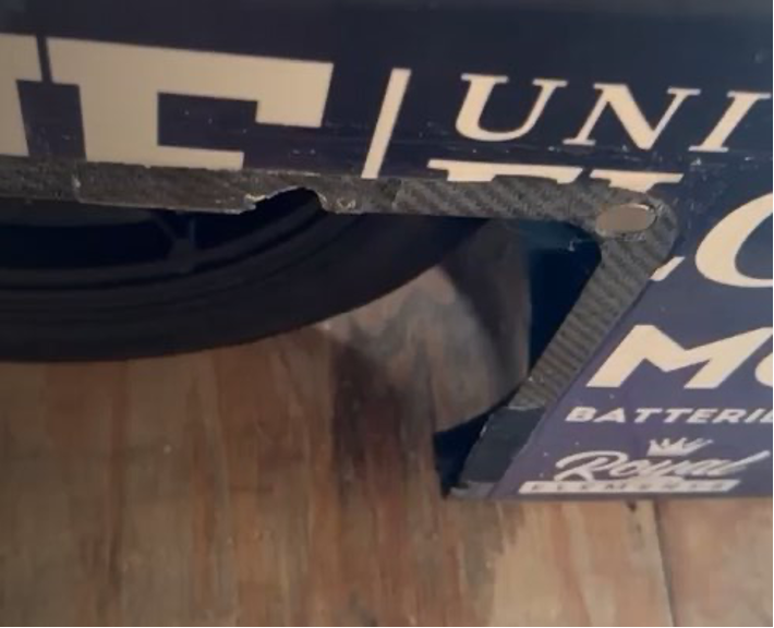 Fig. 1. Picture of previous attachment problems
Basing our design on the comments from competition team members, we chose to adjust the nut-and-bolt design to create our new fairing fasteners. To solve the problem of requiring a team member to reach underneath the car, we designed a nut holder to screw onto the body of the car, which would allow us to thread into a bolt holding the fairing panels onto the car.
|
|
|
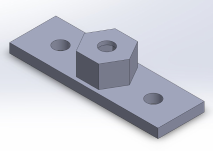
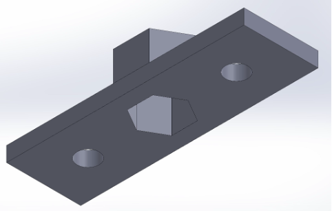
Fig. 2 & 3. First iteration of fairing attachment solution
The competition team members loved this design, but we realized screwing our design onto the body of the car would make the outer body less aerodynamic. Instead we decided to change the design and remove the holes for screws to instead attach the design to the car with epoxy. We reduced the nut holder’s size to be 10-24, based on the nominal screw size the team uses in competition. Finally, we included a taper on the nut holder to distribute shear loads, as we realized angles orthogonal to the z-axis of 3D prints cause low resistances to shear loads, with reaction only coming from layer adhesion.
|
|
|
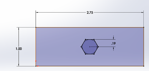
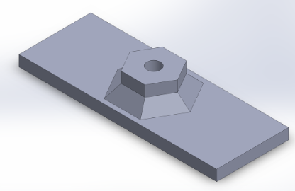
Fig. 4 & 5. Second iteration of fairing attachment solution
We got this iteration of the fairing attachment printed, and went out to the Solar Park to visually test them on the aerobody. The design worked well, but needed some sanding to better fit the sides of the fairing openings that they would need to sit alongside without having any overhanging material.
|
|
|
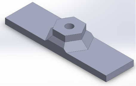
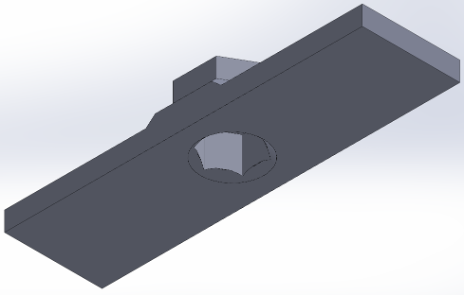
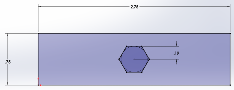 Fig. 6, 7, & 8. Third iteration of fairing attachment solution.
The general design got changed for the final time, decreasing the width to eliminate the need for sanding down the printed design as shown above. Additionally, a single iteration of a fairing attachment was needed in order to fit a lip in one section of the aerobody. Dimensions were taken and a specific fairing attachment was made to fit this spot on the car, with the geometry shown below, to ensure the nut would still be held correctly and be effective as an attachment method.
|
|
|
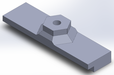
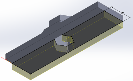
Fig. 9 & 10. Specific iteration of fairing attachment for one spot of the car.