
Manufacturing
Written by: Trevor Bendik
The design process heavily considered manufacturing, such that custom components could be made using 3-axis CNC milling in as few setups as possible. The brake pedal design consisted ofused 3 custom aluminum components, the Pedal, Mount, and Rail [FigureFig. 1-2].2. This page will be split into three major sections by component, respectively.
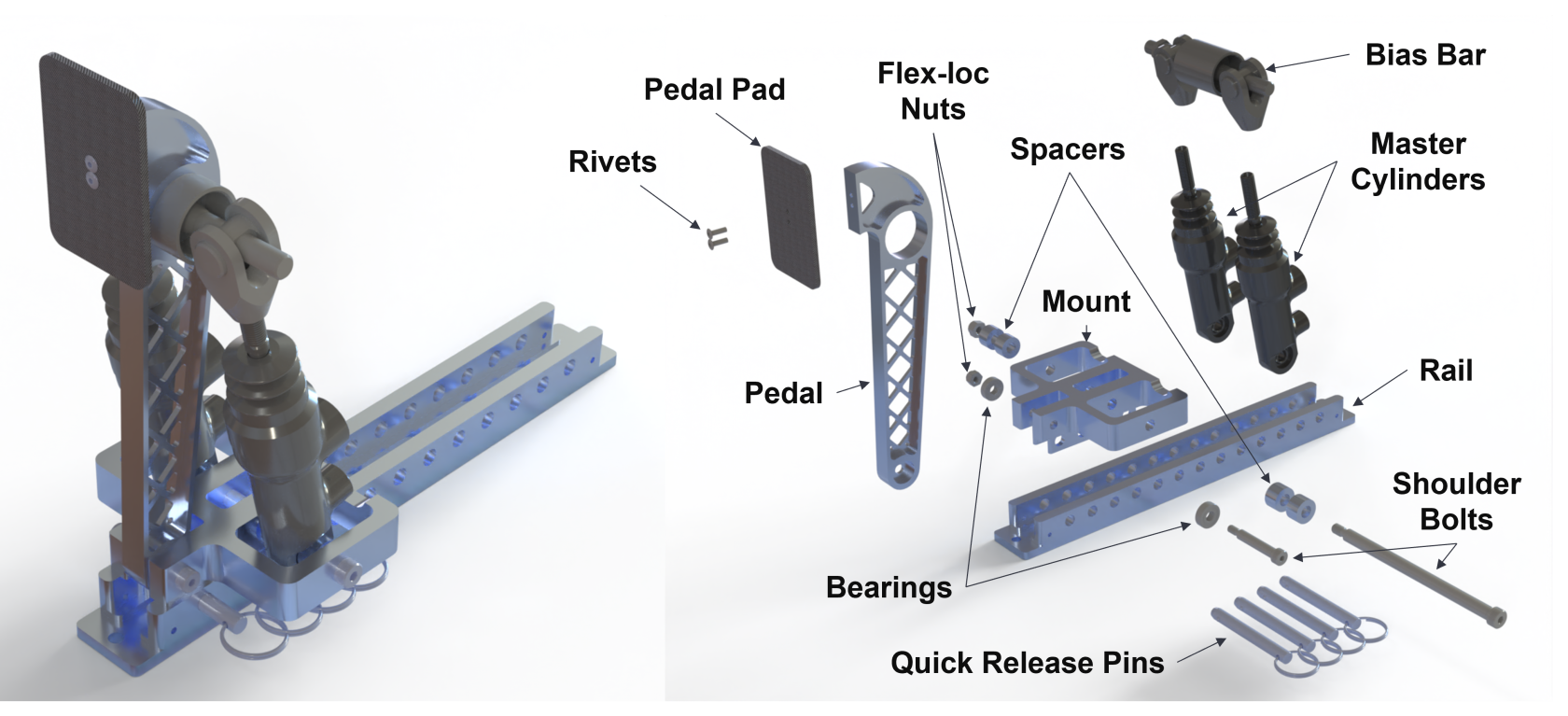
Fig. 1. 2025-2026 Brake pedal design and exploded view with labeled components
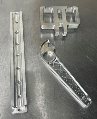
Fig. 2. 2025-2026 Brake pedal custom aluminum components
Pedal
Material: 7075-T651 [Note: T651 is NOT the same as T6, they have different mechanical properties]
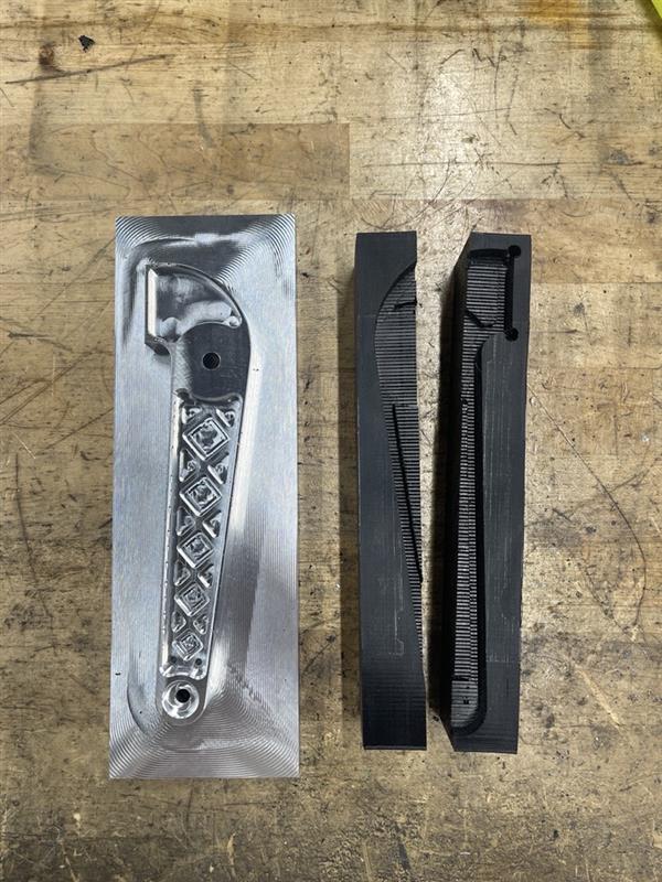
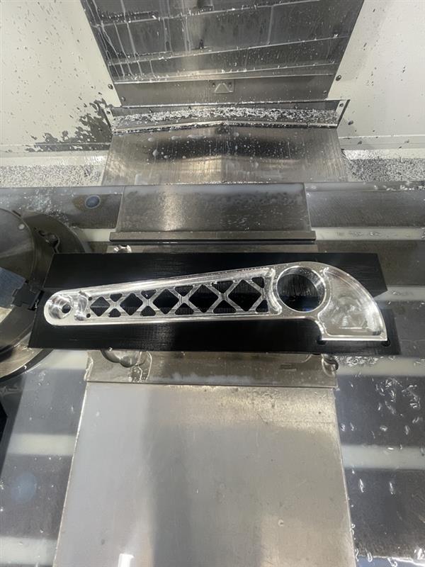
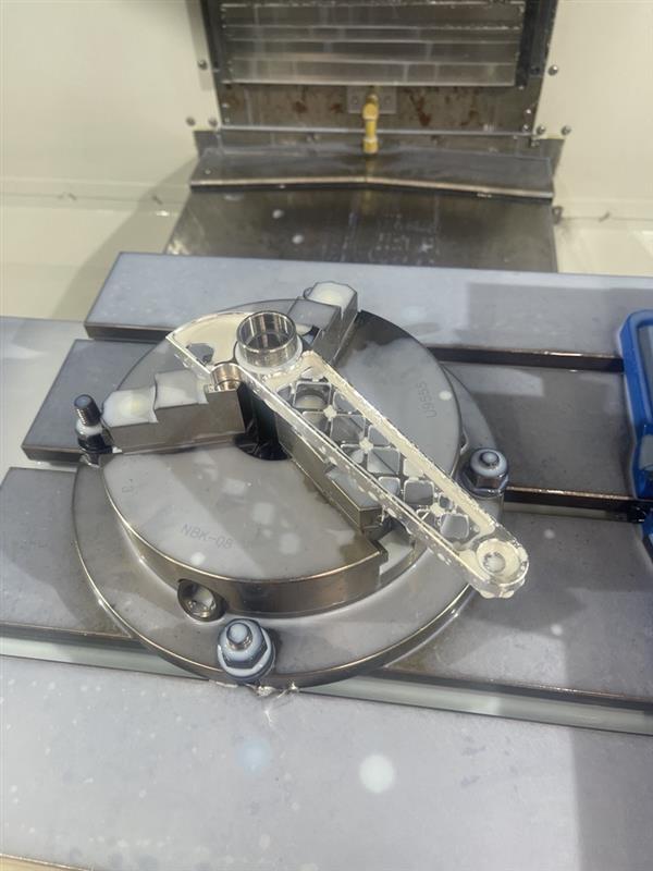
Based on geometry, the part needed a minimum of three setups using 3-axis CNC milling: OP10 (top side), OP20 (bottom side), and OP30 (pedal pad holes). OP20 (bottom side) required custom 'soft-jaws' due to not having 2 parallel flat surfaces for adequate workpiece clamping and positioning. OP30 (pedal pad holes) also required soft jaws to ensure that the pedal pad interface was perpendicular to the drill.
OP10
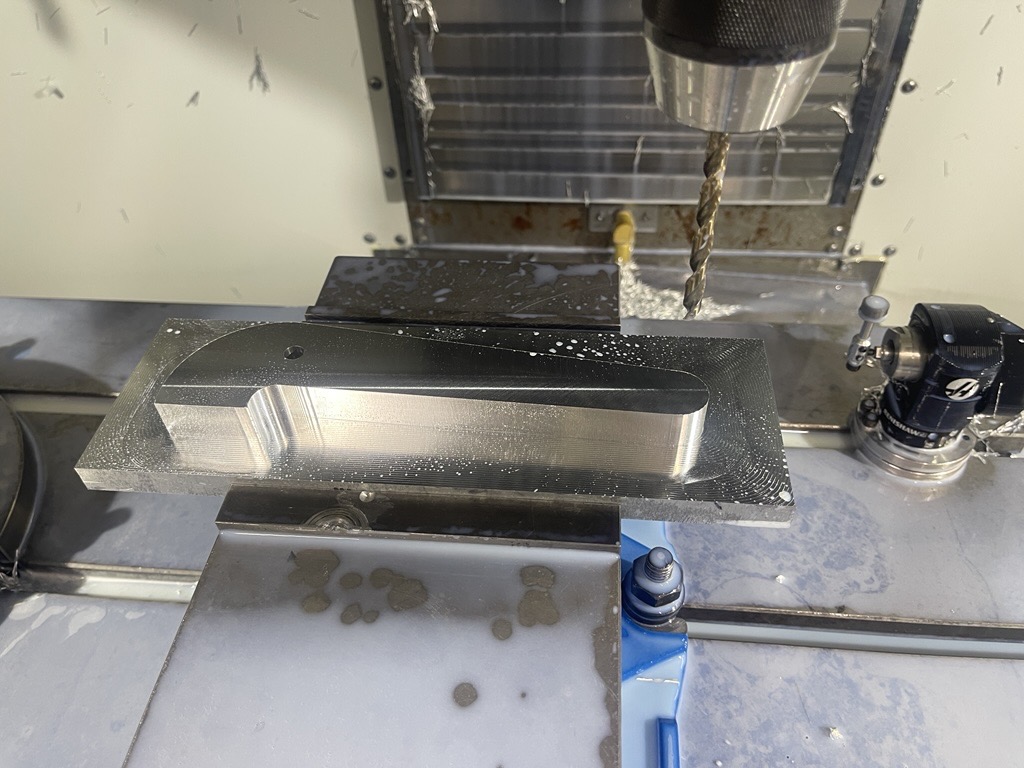
The goal of the first operation is to machine as much as possible. For that reason, a stock block was chosen such that the entire pedal outer counter and onethe top half of the internal webbing could be machined in one go, while leaving adequate clamping area, and at least 0.100" of clearance between the machining bottom height and the top of the vise jaws.
Stock Dimensions: 10.90" X 3.60" X 1.36" [Fig. 3]
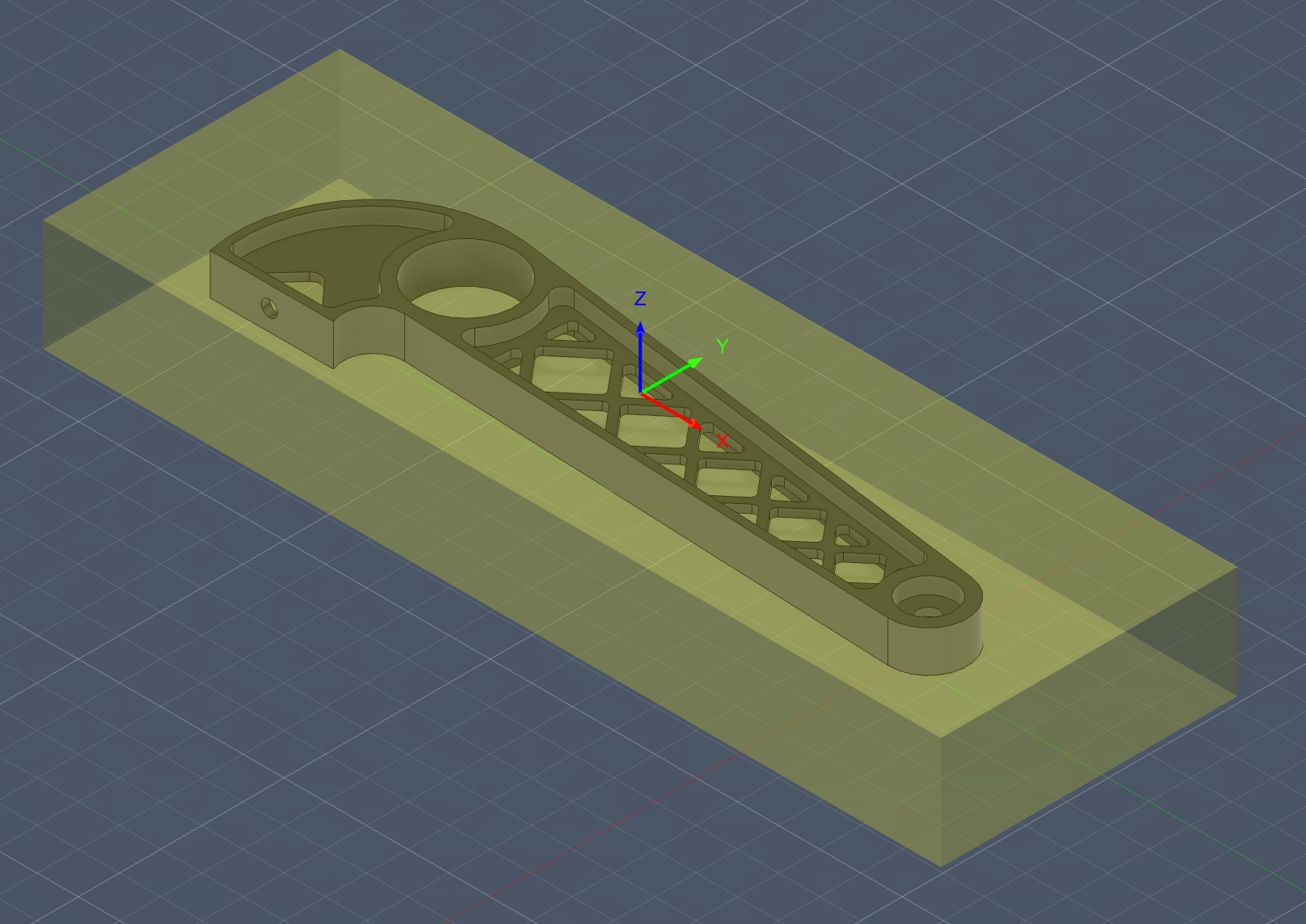
Fig. 3. Autodesk Fusion stock-workpiece set up
The origin for the program is 'Top Center of Block' for easy work offset probing. The model is centered in the X and Y directions, and is offset by 0.100" from top in the Z direction. This was done to enable facing finish passes. The list of OP10 tooling passessequences can be seen in FigureFig. 3.4, starting with 1.1 and ending with 1.17.
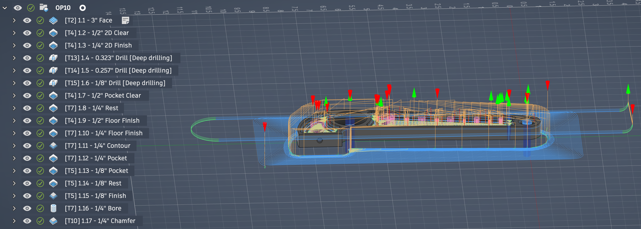
Fig. 4. Autodesk Fusion CAM program OP10
Sequence1.2 and 1.3 have a bottom height of 0.200" below the model. This is to ensure that the contour is milled completely in one pass so there are no subsequent offset issues when it comes to the outer contour. Sequence 1.4 is a drill that passes through the bias-bar bore to be used as a 'machined' surface for probing in OP20. Note that the bias-bar bore is not machined in OP10. That is intentional to maintain workpiece rigidity for clamping in OP20. The bore will get machined in OP20. Note that only 7 tools were used, 1/2", 1/4", 1/8" ZrN coated carbide flat end mills, 0.323" and 0.257" HSS drills, and a 1/4" carbide chamfer end mill
OP20
OP30
OP40
Mount
Material: 7075-T651 [Note: T651 is NOT the same as T6, they have different mechanical properties]
Rail
Material: 7075-T651 [Note: T651 is NOT the same as T6, they have different mechanical properties]