
Manufacturing
Written by: Trevor Bendik
The design process heavily considered manufacturing, such that custom components could be made using 3-axis CNC milling in as few setups as possible. The brake pedal design used 3 custom aluminum components, the Pedal, Mount, and Rail Fig. 1-2. This page will be split into three major sections by component, respectively.
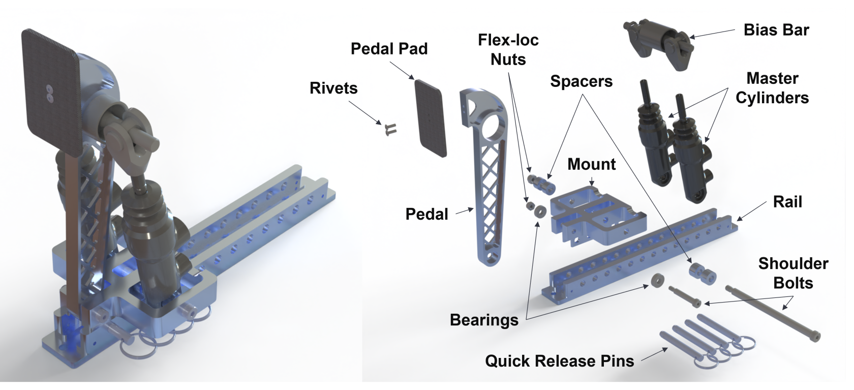
Fig. 1. 2025-2026 Brake pedal design and exploded view with labeled components
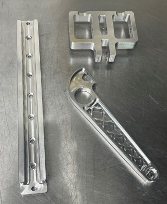
Fig. 2. 2025-2026 Brake pedal custom aluminum components
Pedal
Material: 7075-T651 [Note: T651 is NOT the same as T6, they have different mechanical properties]
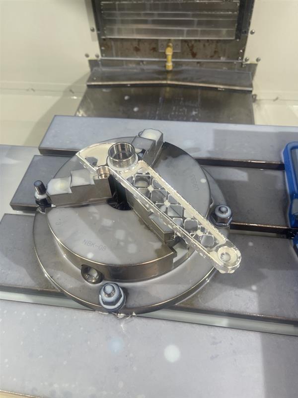
Based on geometry, the part needed a minimum of three setups using 3-axis CNC milling: OP10 (top side), OP20 (bottom side), and OP30 (pedal pad holes). OP20 (bottom side) required custom 'soft-jaws' due to not having 2 parallel flat surfaces for adequate workpiece clamping and positioning. OP30 (pedal pad holes) also required soft jaws to ensure that the pedal pad interface was perpendicular to the drill.
OP10
The goal of the first operation is to machine as much as possible. For that reason, a stock block was chosen such that the entire pedal outer counter and the top half of internal webbing could be machined in one go, while leaving adequate clamping area, and at least 0.100" of clearance between the machining bottom height and the top of the vise jaws.
Stock Dimensions: 10.90" X 3.60" X 1.36" [Fig. 3]
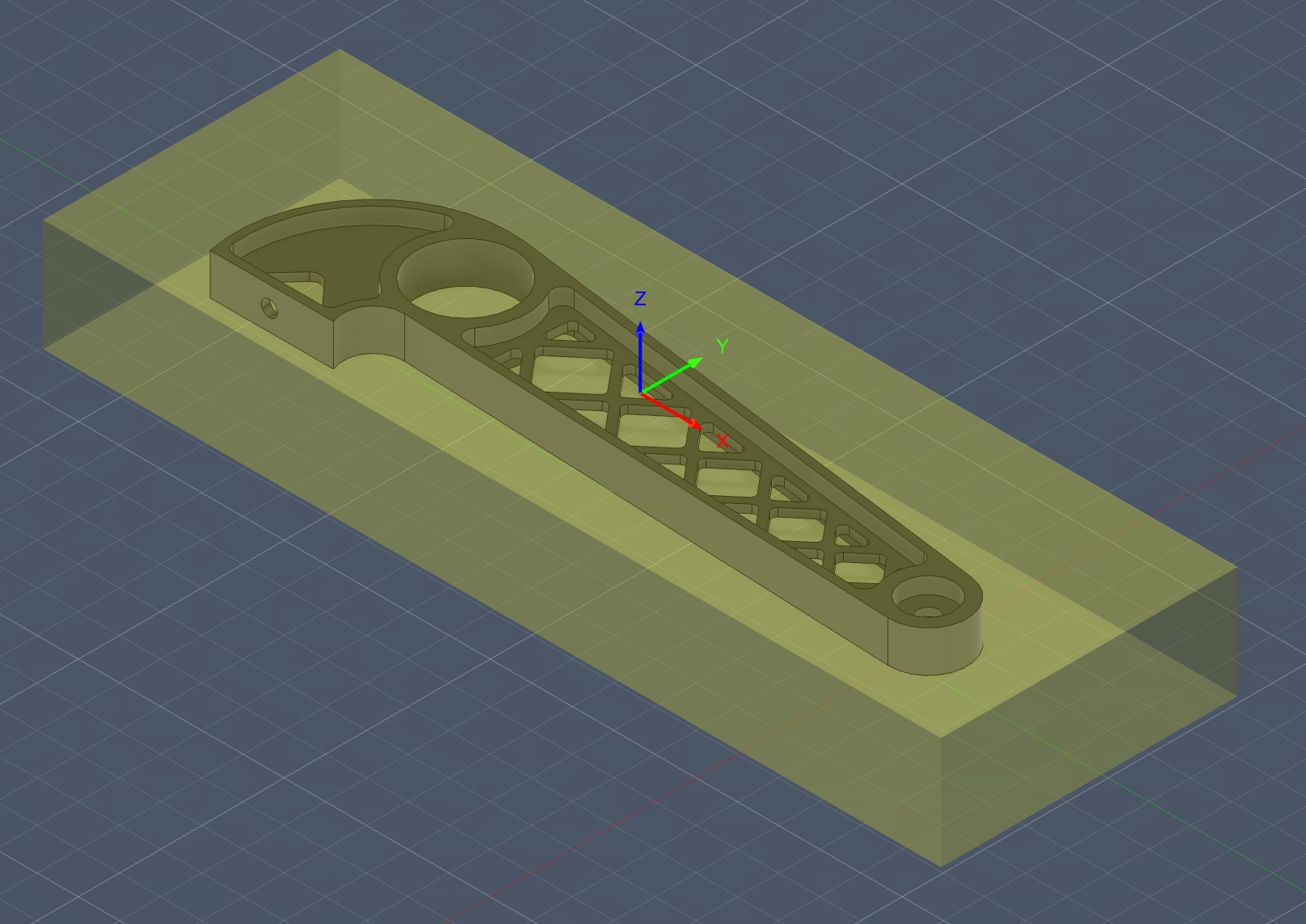
Fig. 3. Autodesk Fusion stock-workpiece set up
The origin for the program is 'Top Center of Block' for easy work offset probing. The model is centered in the X and Y directions, and is offset by 0.100" from top in the Z direction. This was done to enable facing passes. The list of OP10 tooling sequences can be seen in Fig. 4, starting with 1.1 and ending with 1.17.
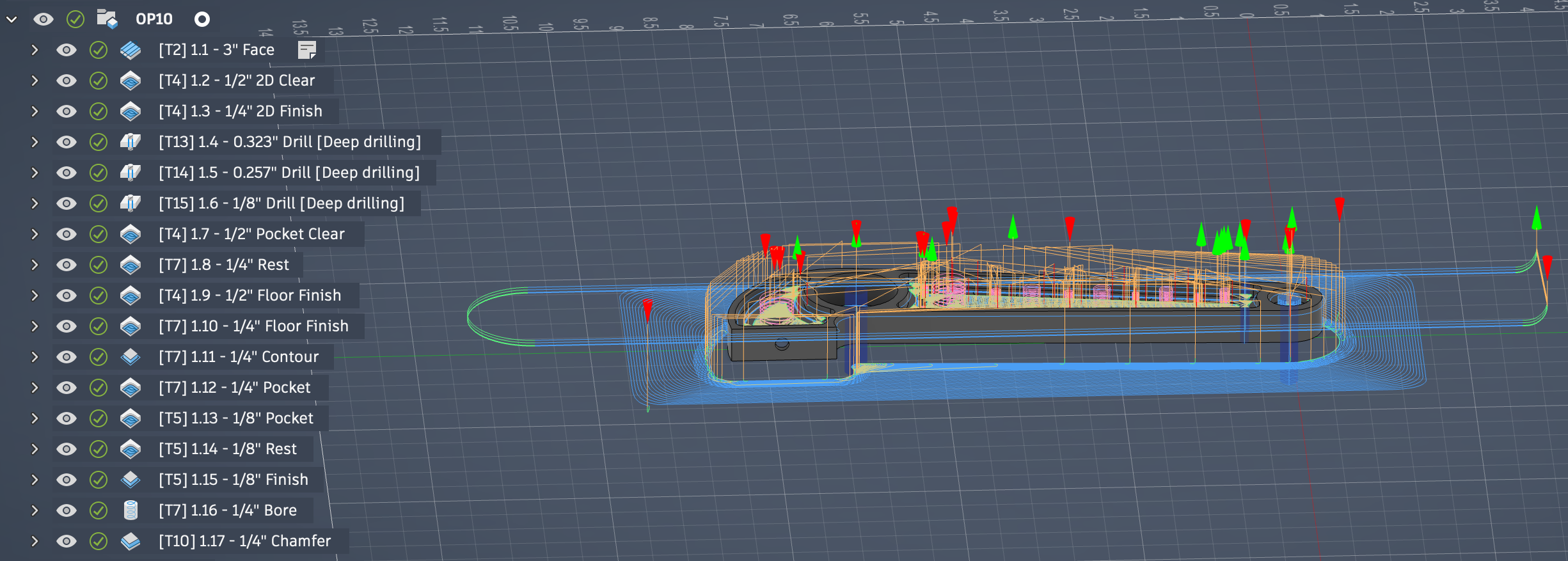
Fig. 4. Autodesk Fusion CAM program OP10
Sequence 1.2 and 1.3 have a bottom height of 0.200" below the model. This is to ensure that the contour is milled completely in one pass so there are no subsequent offset issues when it comes to the outer contour. Sequence 1.4 is a drill that passes through the bias-bar bore to be used as a 'machined' surface for probing in OP20. Note that the bias-bar bore is not machined in OP10. That is intentional to maintain workpiece rigidity for clamping in OP20. The bore will get machined in OP20. Note that only 7 tools were used, 1/2", 1/4", 1/8" ZrN coated carbide flat end mills, 0.323" and 0.257" HSS drills, and a 1/4" carbide chamfer end mill. The completed OP10 product can be seen in Fig. 5.
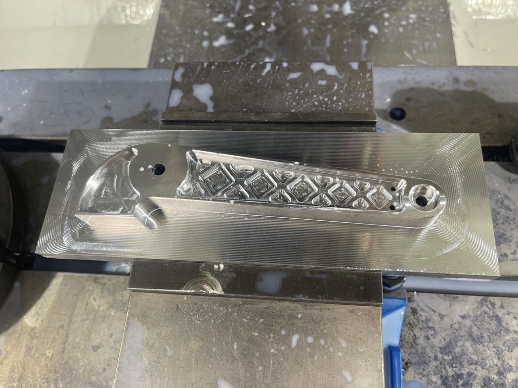
Fig. 5. Completed Pedal OP10
A problem was encountered with the 1.17 chamfering sequence. The program was written to use a 1/4" chamfer mill, but someone had replaced my tool with a 3/8" chamfer mill, and the tool was bigger than expected, and it clipped the contour edges of the pedal when it plunged to chamfer the webbing on the inside pocket.
OP20
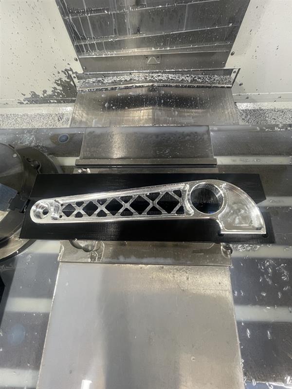
The goal of the second operation is to remove all excess stock, finish the bias-bar bore, and then finish the internal webbing features. First, to do this, a custom soft jaw had to be created, something that secured the workpiece such that the machined features in OP10 were completely face down, and did not add too much compressive stress on the webbing as it was machined out. Additionally, I wanted the webbing to be supported vertically underneath such that chatter/vibrations were minimzed, hence the following soft jaw design [Fig. 6].
FIG 6
FIG 6 CAPTION
To make these soft jaws, raw rectangular blocks were 3D printed out of black PETG. Then, the soft jaw features were CNC machined. This was done to ensure tolerances were met, as 3D printers struggle with dimensional accuracy and necessary printing resolution to meet certain features (even if it claims to be good at all of those things). Its important to note, that the coolant was turned off during this machining, and was periodically sprayed using the coolant hose instead (max 2 times per cycle). This prevented the PETG from getting water logged with coolant and swelling. Had the workpiece swelled, the dimensional accuracy would again be impacted as it shrunk post-machining, and it would have caused offset issues in the OP20 machining cycle.
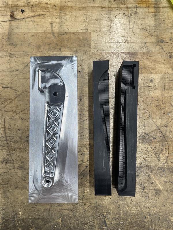
Fig. 8. Post-OP10 workpiece and newly machine custom soft jaws.
OP30
OP40
Mount
Material: 7075-T651 [Note: T651 is NOT the same as T6, they have different mechanical properties]
Rail
Material: 7075-T651 [Note: T651 is NOT the same as T6, they have different mechanical properties]