
How to depict stress
Engineering has 3 primary stages that every project goes through: Design, Analysis, and Manufacturing. While these are 3 distinct stages, their significance is equal at every stage. When designing a component, one should also consider how to analyze and manufacture such a component; during analysis, changes in design to fix failure and how to manufacture around such changes; during manufacturing, how achieve the goals of design and analysis while dealing with the realities on the ground of manufacturing error. This wiki page is intended to give a wholistic understanding of the theory behind design, analysis, and manufacturing around failure mechanics. The 1st section will focus on solid mechanics design and analysis for loads and 2nd section being on composites more specifically.
1. Solid Mechanics
Physics relies on three laws: inertia, F=ma, and force equilibrium. For static analysis, The forces in every component direction (x,y,z) are equal to zero, with boundary conditions to make certain points infinitely stiff/rigid/fixed. The loads experienced on a body are described as normal to the boundary condition (axial)(1) or non-normal to the boundary condition (moment)(2). The only restriction to this method is the requirement to be the number of conditions to be equal or less than the number of component force equations. Generally, the primary method for solving static problems is to take component forces equal to zero in each direction and moments about any point equal to zero to solve for all condition. This is described in more detail and with problems in statics.
|
|
(1) |
|
|
(2) |


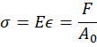
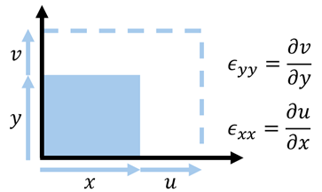
Solid Mechanics/Mechanics of Solids/Mechanics of Materials describes static problems that can be solved with more unknowns than component force equation, using elasticity. MoM describes the internal forces at a point with a 2nd order tensor, called "Stress". Stress is a loose concept that describes the internal forces at a point, with it also being found by the gradient of deflection across elements of a solid. The formulas for engineering stress are described as elasticity/stiffness times strain and as force over area (1). Green-Lagrange/Extensional Strain, , is the change of length of a specimen divided by the original length (2). Stiffness,
 , is a value describing a material’s resistance to deformation. The other form uses force,
 , applied divided by some constant area,
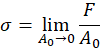
 . The force over area variation is actually average engineering stress across a constant area, so for an accurate stress value to be true the distribution of stress across the area must be the same. Finite element method decomposes geometry into a mesh with elements of ever decreasing area to zero, which is where stress singularizes occur as the model converges and the stress goes to infinity (3). This stress described is stress about the normal axis defined by a given plane, called normal stress.
|
|
(1) |
|
|
(2) |
|
|
(3) |

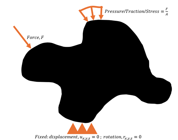
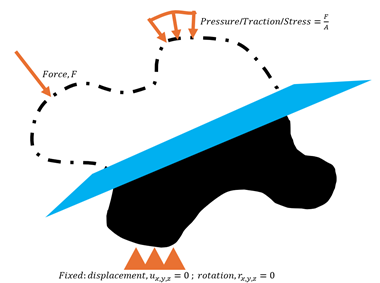
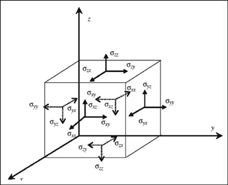
Given a body (Fig. 1), how would someone find stress? First, the boundary conditions can be fixed: displacement in every direction equal to zero and rotation in every direction equal to zero. Load can be applied as a force at a point, force across a length, or force across an area; these three methods are interchange able for applying a load on a body with each method only applying unity for any given length unused (unity is any value equal to 1, so force across length will have a depth equal to unity/1).
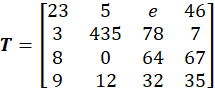
To find stress, we must first go over how stress is a 2nd order tensor. A tensor is an array with an implied magnitude and an order equal to the dimensions applied. So, a scalar/magnitude will be a 0th order tensor (1); a 1st order tensor will be an array of magnitudes with columns (2); a 2nd order tensor will be an array of magnitudes with rows and columns (3). Stress is a 2nd order tensor, with the first dimension being a plane to take stress on and the second being a direction to take stress in (4); 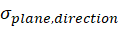 .
.
Normal stress, ,is stress taken about the normal vector/direction, and Shear stress,
 , is stress taken about any other unit vector/direction. Normal stress applies a linear elastic response/normal strain (
 ), which was described previously as change of length over original length. Shear stress applies a distortional elastic response and describes shear stain (
 ) as the change of angle between two originally orthogonal axes (5).
|
|
(1) |
|
|
(2) |
|
|
(3) |
|
|
(4) |
|
|
(5) |




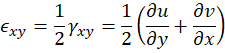
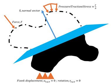
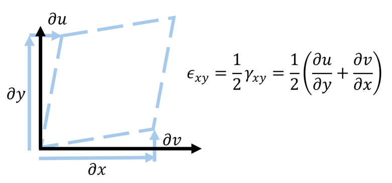
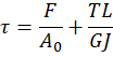
The core idea for normal and shear load/stress/strain, is how normal loading applies linear response and equation and shear applies distortional response and equations. For design, one should view loads as either normal or shear. With normal loads being applied from axial (on axis is when the normal vector is in the direction of the load) or bend-moment loads (1). Shear loads are applied via off-axis (off axis referring to when the unit vector is taken not in the direction of the load) or torsional loads (2). Stress is taken at a point that can be represented in the form of 3 mutually perpendicular planes with associated stress and strain components. For more reference of how to solve for stresses in real problems, look for combined loading problems in mechanics of materials textbooks.
|
|
(1) |
|
|
(2) |
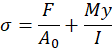
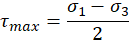
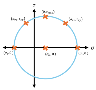
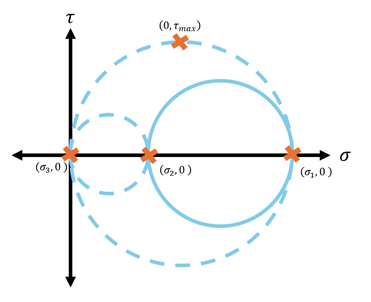
Now we know what stress is an how to find it, but how do we find max stress. For 2D problems, this can be done with a Morh’s circle/Morh space. The axes are normal stress in the x and shear stress in the y. You can apply your state of stress on the plot and find the maximum stress/principal stresses, ,(where shear is zero) and find the maximum shear stress,
 . You find the principal stresses by transforming the stress state into the principal direction using stress transformation (1). This can be seen as transforming the stress tensor into a tensor with no shear stress components, as principal stress are mutually perpendicular unit vectors so long as the principal stresses are distinct from one another. The maximum shear stress is found as the midpoint between the first and third principal stresses - as they descend in magnitude from 1 to 3 (2). Principal stresses can also be found using invariants and factors of zero, values that do not change with coordinate system (3).
|
|
(1) |
|
|
(2) |
|
|
(3) |





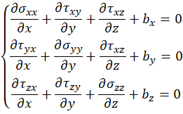
Solid mechanics uses an elastostatic boundary value problem, where the strains can be found once the displacement are determined using strain displacement relations, and stress can be found using constitutive relations. These kind of problems involve solving 3 equilibrium equations in conjunction with strain-displacement relations and constitutive relations. The boundary conditions need to be provided in terms of given displacements or prescribed forces.
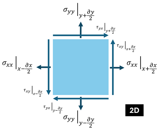
There are 6 stress functions that can not be arbitrary and are calculated using stress equilibrium equations, these equations are called stress fields (1). The assumptions are that the out of plane stress is unity and there are body forces (gravity and such). They are solved by taking the 2nd order Taylor series approximation of the differential stress element.
|
|
(1) |
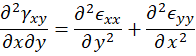
A set of any 3 nonsingular functions will represent a possible displacement field. The forces required to produce the resultant displacement may be complex but possible, this is not the case for stress or strain. The six strain functions must satisfy 3 compatibility equations, with 1 given as (2).
|
|
(2) |
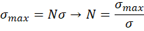
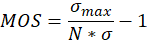
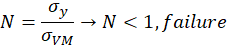
Now that we can find stress, how do we know when a material has failed? A material has failed when the applied stress passes a threshold called the maximum stress or another factor equivalent to maximum stress. This is usually in form of strength ratios/safety factors,  , (1) with a following margin of safety,
 , (2). When the strength ratio goes below 1 the material has failed, and how far the factor of safety is to the desired factor of safety can be seen with the margin of safety. Both are expected to be shown for all analysis work.
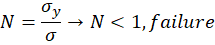
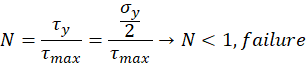
The Theoretical maximum stress/strength a material can take is one third it’s stiffness (the strength required to split atoms); however, this is far beyond the strength of any material we see. This is due to metals failing from atoms slipping not splitting, and brittle material having large discontinuities, voids, fracturing, and other defects that amplify the stress by large amounts. Ductile materials fail in shear stress and brittle materials fail in normal stress; we can distinguish this by transforming the stress matrix into two constituent forms called the volumetric/hydrostatic stress matrix and the distortional stress matrix. They volumetric stress matrix is defined with hydrostatic stress (2), this matrix does not contribute to ductile failure because ductile failure only occurs from distortional stress. This result of this is brittle materials typically only looking at maximum stress the material can withstand, yield/ultimate stress  , called maximum principal stress failure criteria (5) and ductile materials using maximum shear stress (6) or von-mises/distortional energy (7) failure criteria.
|
|
(1) |
|
|
(2) |
|
|
(3) |
|
|
(4) |
|
|
(5) |
|
|
(6) |
|
|
(7) |



2. Composites
working on it