
2: Mechanical Model System
After adding the geometry system, The next component system that should be added is the mechanical model system. This system lets you assign the material, mesh, mesh controls, and named selections.
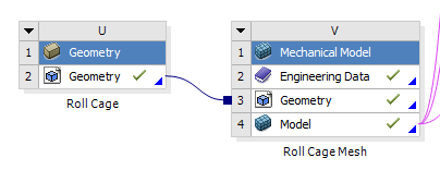
Fig 1. Adding a mechanical model system (right) and linking it to the geometry system
To link the system, click and hold on the geometry step in the geometry system and then drag over to the geometry step in the mechanical model system. We do this so that for more complicated projects you can link the geometry to multiple mechanical models.
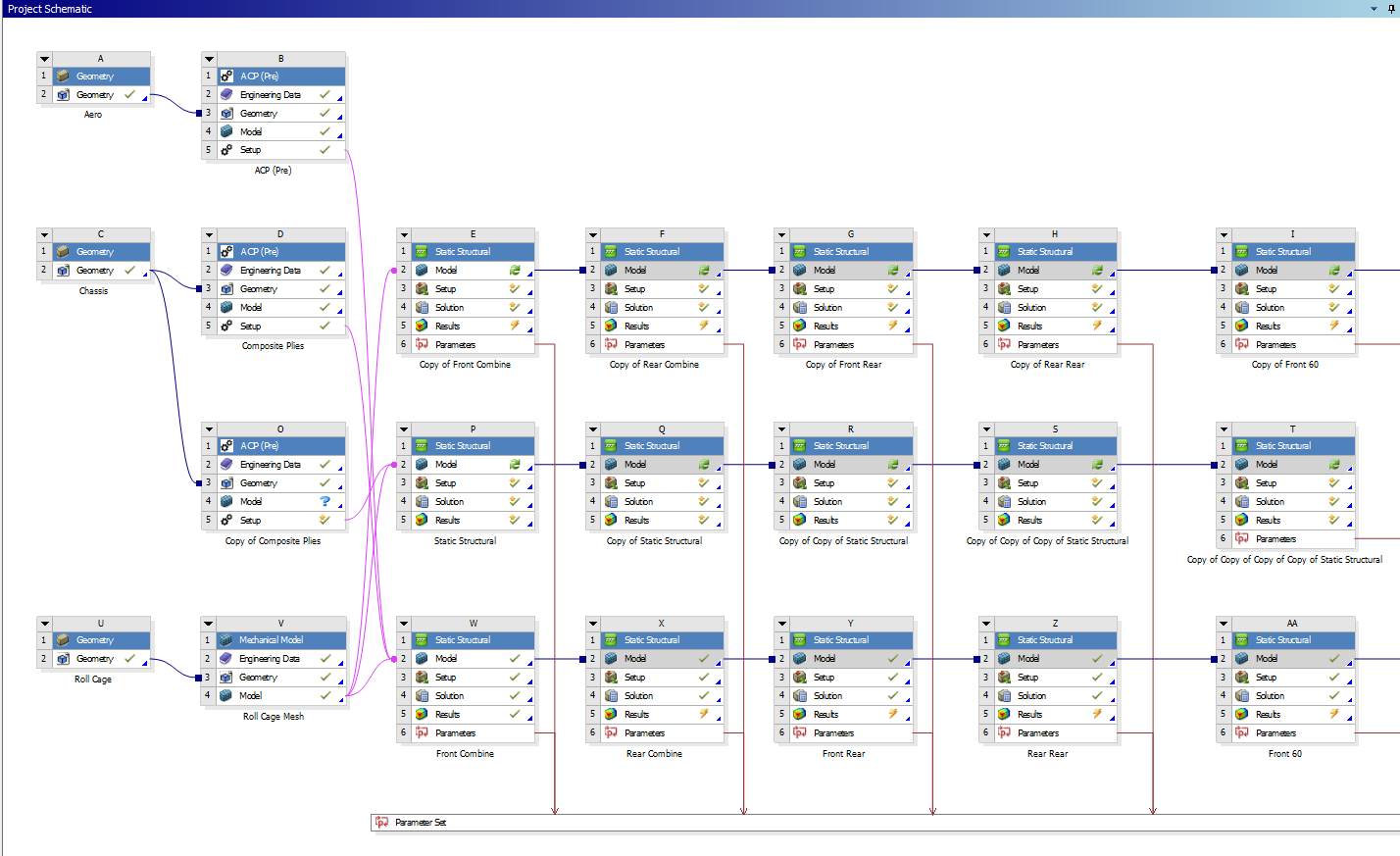
Fig 2. A more complicated project
MATERIALS
Engineering data allows you to select the materials available to apply to your geometry. It will open the materials in the project currently. If plan on using a default material (such as an aluminum or steel alloy) you can skip this step and just add it later in the model step. If you are using a special custom material (such as welded 4130 or carbon fiber-epoxy), it is advisable to add it here.
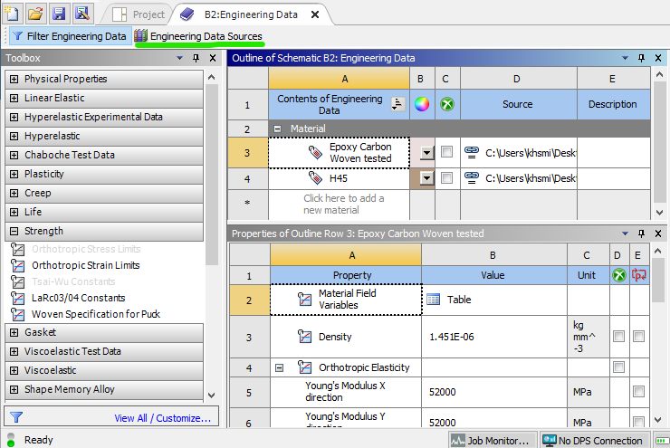
Fig 3. Engineering data page
To select a material, go to engineering data sources (green). This will open a few libraries of materials. You can add one of these existing materials, or create a custom library and then add a custom material. To add a custom material, hit the check box circled in green in figure 4.
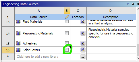
Fig 4. A custom library
Once you have created and named your new custom material, add material properties from the toolbox on the left. Some common ones are under the Linear Elastic and Strength headers. The only values the are required for an isotropic material (such as aluminum or steel) are its elastic modulus and Poisson's ratio, which are added with the Isotropic Elasticity property.