
2: Mechanical Model System
After adding the geometry system, The next component system that should be added is the mechanical model system. This system lets you assign the material, mesh, mesh controls, and named selections.
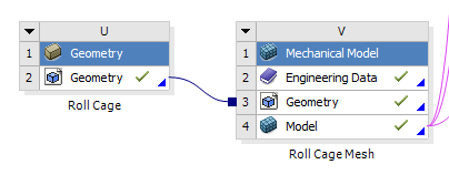
Fig 1. Adding a mechanical model system (right) and linking it to the geometry system
To link the system, click and hold on the geometry step in the geometry system and then drag over to the geometry step in the mechanical model system. We do this so that for more complicated projects you can link the geometry to multiple mechanical models.
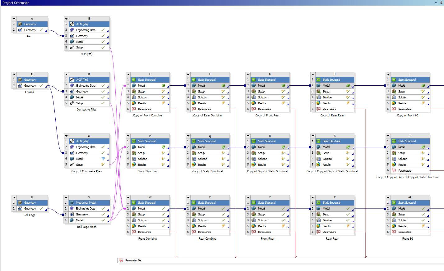
Fig 2. A more complicated project (chassis)
MATERIALS
The engineering data step allows you to select the materials available to apply to your geometry. It will open the materials in the project currently. If plan on using a default material (such as an aluminum or steel alloy) you can skip this step and just add it later in the model step. If you are using a special custom material (such as welded 4130 or carbon fiber-epoxy), it is advisable to add it here.
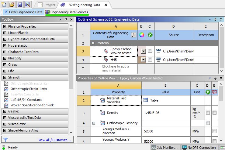
Fig 3. Engineering data page
To select a material, go to engineering data sources (green). This will open a few libraries of materials. You can add one of these existing materials, or create a custom library and then add a custom material. To add a custom material, hit the check box circled in green in figure 4.
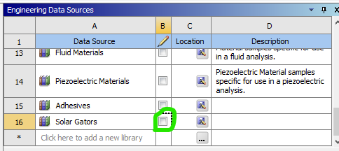
Fig 4. A custom library
Once you have created and named your new custom material, add material properties from the toolbox on the left. Some common ones are under the Linear Elastic and Strength headers. The only values the are required for an isotropic material (such as aluminum or steel) in a typical static structural finite element model are its elastic modulus and Poisson's ratio, which are added with the Isotropic Elasticity property. Yield strength / ultimate strength are required for a factor of safety plot, which may be a result of interest later.
GEOMETRY
This step should already be filled from linking to the geometry system.
MODEL
Opening the model step will open an instance of Ansys Mechanical. This is the actual software where the "action" occurs. To move forward and actually analyze the model, all blue question marks must be turned to green checkmarks.
Material assignment
First, materials must be assigned to bodies in the model, either by part or by body. Any material added to engineering data should be available to choose, otherwise use the search bar and materials will be generated via Ansys Granta.
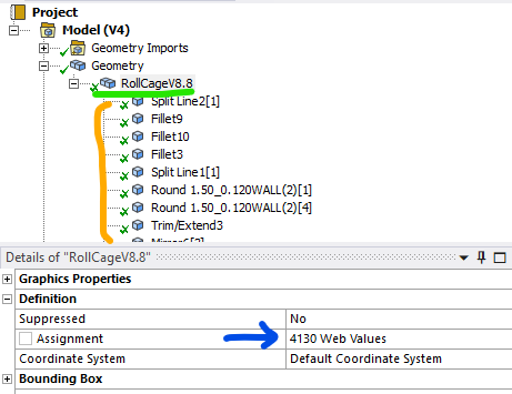
Fig 5. Material is assigned by the blue arrow, either by part (green) or by each individual body (orange).
The materials folder under that is typically not used. The coordinate system folder can be used if you plan to utilize reference points or special coordinate systems for displacement in your model analysis.
Connections
Next, if you have multiple bodies, it is important to verify your connections. Ansys typically automatically generates these, but sometimes they can be wrong. Bad contacts can give massive errors in a model. By default all contacts are assumed to be bonded, i.e. the items are glued together on all 6 degrees of freedom. There are other options for more advanced behavior, but that is not covered here. There are also options for joints, beams, bearings, and springs, which is also not covered here.
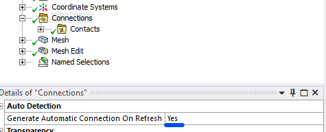
Fig 6. If you want to disable automatic contact generation, change this to NO
Mesh
Lastly, the geometry must be meshed. There are entire research papers dedicated to the best ways to mesh things, and hopefully multiple pages on this wiki (one day), but this will just cover the basics. What is important to know is that a bad mesh can give bad results, so it is important to make sure it properly represents your part.
Meshes are made up of nodes (think the points that connect the lines) and elements (the shapes the connected lines make). There are many different types of elements based on where the nodes are placed, and what geometry is being modeled. 3D parts use either tetrahedrons (triangular pyramids) or hexahedrons (rectangular prisms). 2D parts use either triangles or quadrilaterals. There are also transition elements that exist if a model has both kinds, which is sometimes unavoidable.
Physics preference: Mechanical is the default, and should stay that way unless you are attempting to mesh parts with high amounts of curvature (aeroshell) without mesh control.
Element order: Linear elements only have nodes in the corner. Quadratic elements have a node in the middle of each line. Therefore, linear elements can only model constant strain while quadratic elements can model linear strain. More on that here. A rule of thumb is if you are worried about bending stresses, you either need a very fine linear element model or a less fine quadratic model. It is typically less computationally expensive to use the less fine quadratic model.
Element Size: Element size depends heavily on the model in question. The default size it typically too coarse, but can be a good start for a first run of the model.
These 3 settings are the only basics you need to understand before hitting the generate button.
For additional control, you can right click mesh and insert mesh controls. These are more advanced features which can control where the mesh is seeded from, how it is mapped across faces, and what element method is used. More info on that can be found here.
Mesh Edit
For some models, mesh edits may be necessary. The most common is node matching. This moves nodes between contacting bodies to the same location, which will decrease solution inaccuracy while maintaining mesh and solution speed.
Named Selections
Named selections simply allow you to group bodies, faces, edges, and vertices into a named group that you can call later in your analysis. They are not necessary for most models (required for ACP), but can greatly improve your workflow by minimized the number of times you have to select a large number of items.
FINAL NOTES
A common question is whether to combine all bodies in a model or leave them separate before importing to Ansys for analysis. At the time of writing I (Kurt, Feb 2025) am of the belief that keep the bodies separate is far superior, as long as a fine enough mesh and node matching are used. When bodies are separate, each one's mesh is able to be seeded and verified separately, which means the entire part can be meshed faster. Additionally, the solver can compute each body independently much faster than when all of the bodies are linked.
No comments to display
No comments to display