
Getting Started with Workbench
Why Ansys?
Ansys is not a program like Solidworks. Rather than having a single viewport to your model open at all times that lets you perform a wide variety of functions, Ansys is segmented into different programs such as mesh, mechanical, and ACP that are accessible through whatever systems you drop into your workbench project.
While this may seem more obtuse than Solidworks where you can quickly take your part and set up a basic simulation, there are many advantage to using Ansys. For example, chassis and roll cage require over 20 simulations of 50+ individual bodies that need to be imported through 3 different part files. Solidworks would require a full reset of the entire model every time a change is made, but with Ansys precise automatic control over what is updated can be done. It also posses much more optimized meshing and solving software that will run better on most computers with less errors. Therefore, we try to use Ansys as much as possible.
What am I looking at?
Ansys starts in Workbench. You may be thinking, what does this have to do with FEA? Where's the CAD model?
In the middle is your project schematic. On the left are your systems. There are a couple kinds of systems, we primarily use the first two:
- Analysis Systems: deal with actual simulations. Most commonly used are Static Structural systems, which deal with the deformation of a system that does not move. Think of a person standing on a bridge.
- Component Systems: deal with setup of the model before putting it into an analysis system. ACP(pre) is very important for composites (chassis), while the geometry and mechanical model systems are very important for structuring efficient workflows (more on that later).
Systems can be dragged and dropped onto the schematic, and links can be dragged between them to create workflows (black and pink lines), where different systems feed data into each other. See how the geometry systems each feed into a mechanical model system, and then 3 mechanical models are combined into 1 before being fed into the actual analysis system. This may seem overly complicated, but is very important to keep the time it takes to reset each simulation every time a part is updated to a minimum.
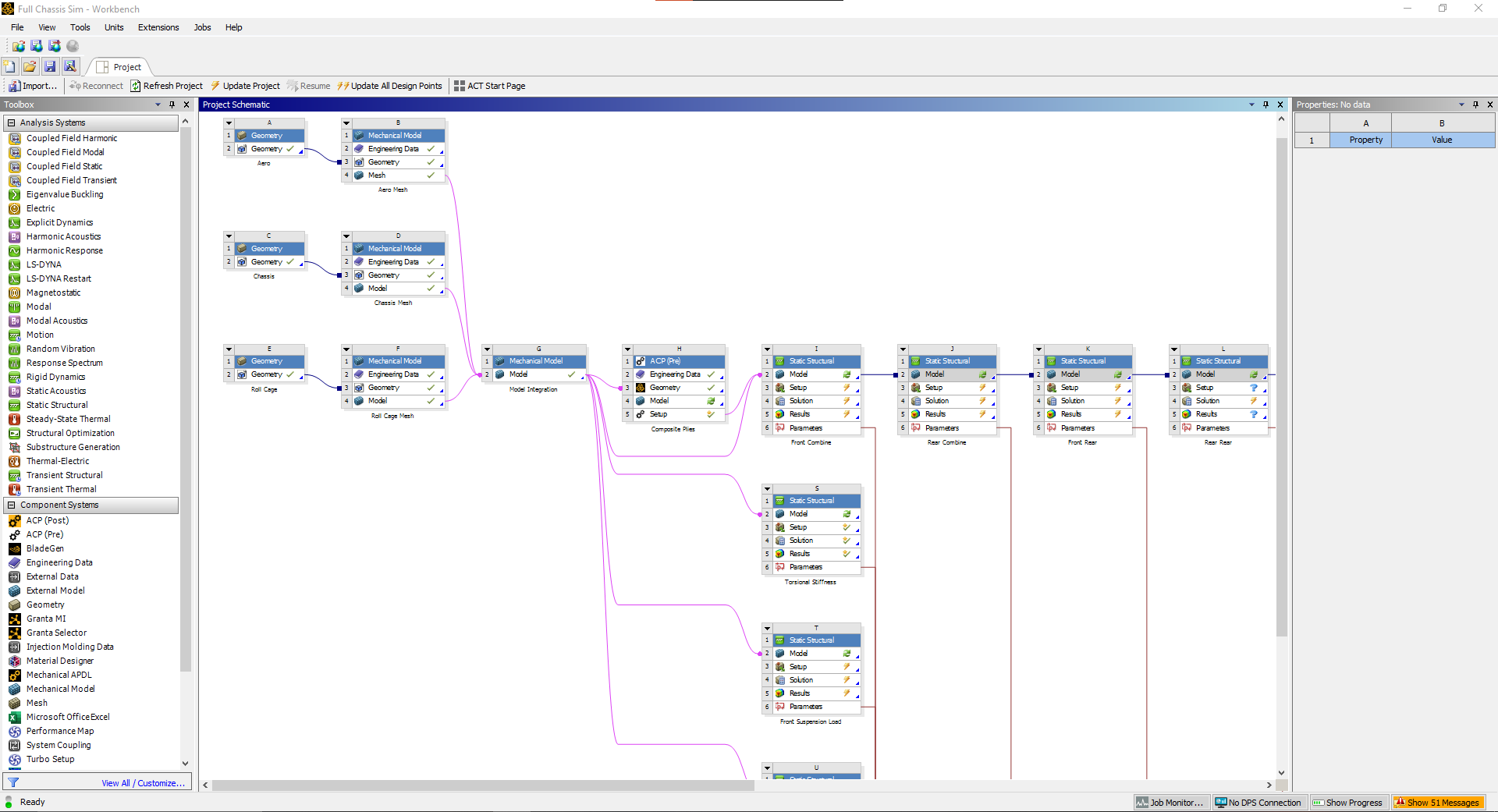
Fig 1. An early example of the full chassis simulation workflow
The systems' properties can be configure on the right panel. Different systems have different options, and will be important for filter what data gets sent to the connected systems
Finally, the red lines feeding out of the analysis systems are parameters (more details later). But basically they simply input/output data in a table format for easy changing of the model or checking if stress is acceptable across iterations.
No comments to display
No comments to display